ELECTRICAL
EQUrPIMENT
(v) Fit the capacitor into position,
on earlier models the eyelet on
the other end of the contact
breaker earthing lead is held under
the capacitor fixing screw. Place
the fixed contact plate in position
and secure lightly with securing
saew(s), One plain and one
spring washer must be fitted under
each of these screws.
(vi) Place the insulating washers on the
contact breaker pivot post and on
the pillar on which the end of the
contact breaker spring locates.
Refit the contact breaker lever and
spfing.
(vii)
Shde the rubber terminal block
.
,
into its slot.
(viii) Thread the low tension connector
and capacitor eyelets on to the
insulating piece, and place these
on to the pillar which secures the
end of the contact breaker spring.
Refit the washer and securing nut.
(ix)
Set the contact gap to 0.014" to
0.016" and tighten the securing
screw(s) of the fixed contact plate.
(X)
Refit the rotor arm, locating the
moulded projection in the rotor
arm
with the keyway
in
the shafi
and pushing fully home. Refit the
moulded cover.
(h)
Replacement Contacts
If the contacts are so badly worn that
replacement is necessary, they must
be
renewed as a pair and not individ-
ually. The contact gap must be set to
0.014" to 0.016"
;
after the first
500
miles running with new contacts fitted,
the setting should
be
checked and the
gap reset to 0.014" to 0.016". This
procedure allows for the initial
"
bedding-in
"
of the heel.
ADLAMPS-MODEL
F700
IMK/VI
General Description
The lamps incorporate a combined reflector
and front lens assembly known as the Lucas
Light Unit. They
are
fitted
with
a
"
pre-
focus
"
bulb which ensures that the filament
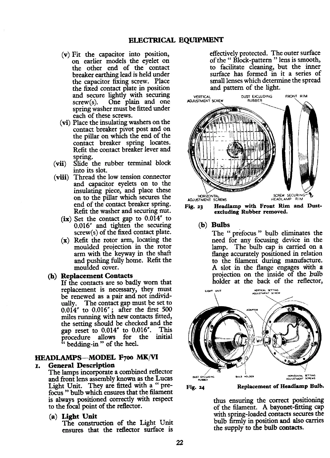
effectively protected. The outer surface
of the
"
Block-pattern
"
lens is smooth,
to facilitate cleaning, but the inner
surface has formed in it a series of
small lenses which determine the spread
and pattern of the light.
VERTICAL
DUST EXCLUDING FRONT RIM
ADJUSTMENT XREW
RUBBER
\
V
v
MRIZONTAL
SCREW
SECURING*
ADJUSTMENT SCREWS
HEADLAMP
RIM
Fig,
q
Headlamp
with
Front
Rim
and Dust-
excluding Rubber removed.
(b) Bulbs
The
"
prefocus
"
bulb eliminates the
need for any focusing device
in
the
lamp. The bulb cap is carried on a
flange accurately positioned
in
relation
to the filament during manufacture.
A
slot
in
the flange engages
FMI
a
projection on the inside of the bulb
holder at the back of the reflector,
ucn
uun
K~T-
SETTING
WST
EXCWDINC
eum
aiaa
-I*.,*TY
SETTING
*"W*
AWYnULm
YlCll
Fig.
4
Replacement of Headlamp
Bulb.
is alwa
s
positioned correctly with respect
r
thus ensuring the correct positioning
to the
ocal
point of the reflector.
of the filament.
A
bayonet-fitting cap
(a) Light Unit
with s ring-loaded
wntaas
secures the
The construction of the Light Unit
bulb
&mly
in position and also carries
ensures that the reflector surface is
the supply to the bulb contacts.
 Loading...


