ELECTRICAL
EQWMENT
2.
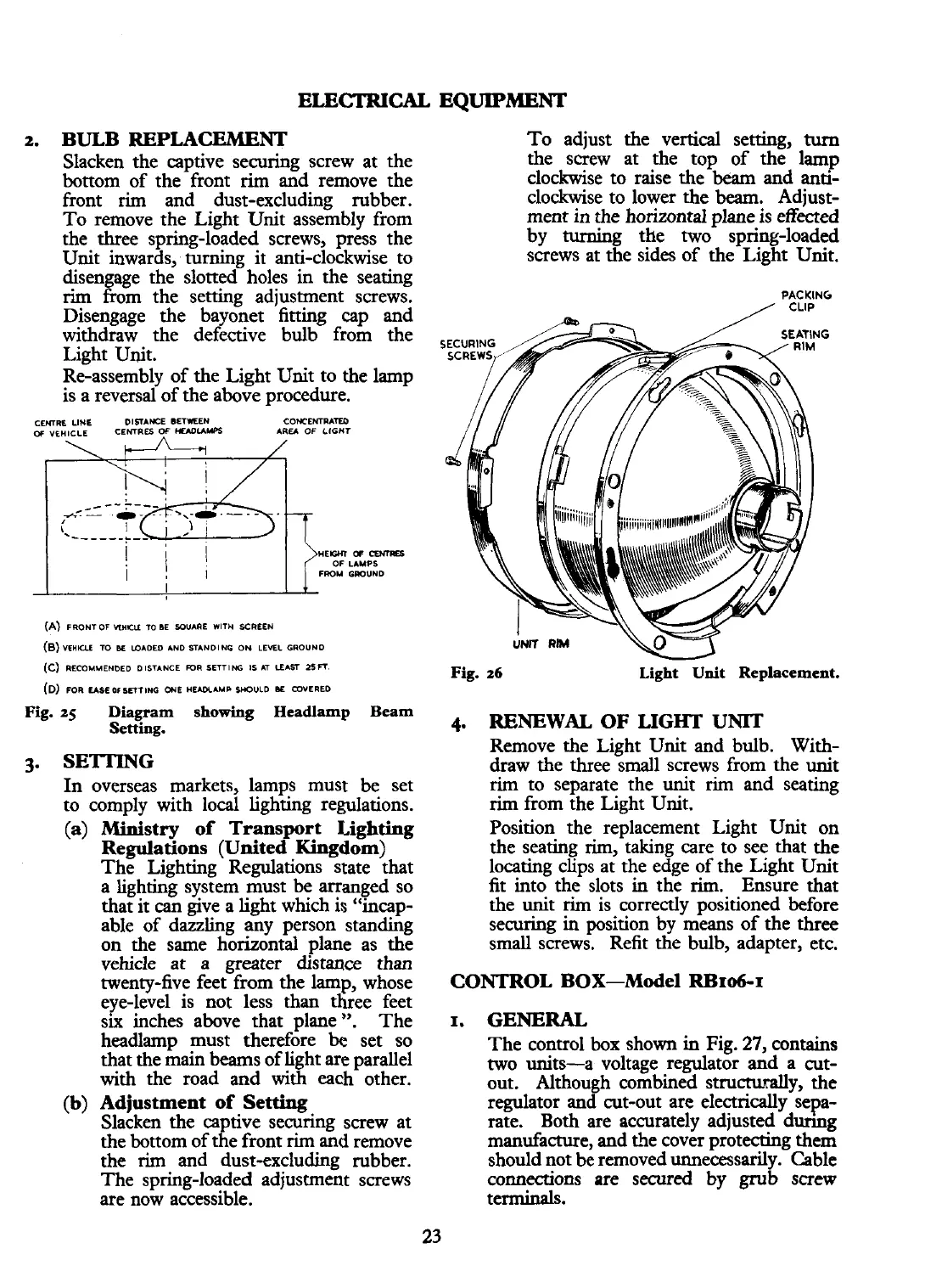
BULB REPLACEMENT To adjust the vertical setting,
turn
Slacken the captive securing screw at the
the screw at the top of the lamp
bottom of the front
rim
and remove the
clockwise to raise the
beam
and anti-
front
rim
and dust-excluding rubber. clockwise to lower the
beam.
Adjust-
To remove the Light Unit assembly from ment in the horizontal plane is effected
the three spring-loaded screws, press the by turning the two
springloaded
Unit inwards, turning it anti-clockwise to screws at the sides of the Light Unit.
disengage the slotted holes in the seating
rim
from the setting adjustment screws.
PACKING
Disengage the bayonet fitting cap and
withdraw the defective bulb from the
G
Light Unit.
Re-assembly of the Light Unit to the lamp
is a reversal of the above procedure.
CEMRL
LINE DISTAWCE BETWEEN CONCENTMM
AREA
OF
LIGHT
WElCYT
ff
CEhlRB
OF LAMPS
FROM GMUND
(A)
FRONTOF
WlUL
TO
M
SOUARE
WlTU
KREEN
(8)vr~Klt
X)
M
WADED AND STANDING ON LEML GROUND
(c)
RECOUMEH~ED
DISTANCE
-R
SETTING
IS
AT
LEm
zsn.
Fig.
26
Light Unit Replacement.
(D)
FOR EASEOISEfTING ONE
H-AMP
SHOULD
M
COVERED
Fig.
25
Diagram showing Headlamp Beam
Setting.
4.
RENEWAL
OF
LIGHT
UNIT
Remove the Light Unit and bulb.
With-
3.
SETTING
draw the three small screws from the unit
In overseas markets, lamps must be set
rim
to separate the unit
rim
and seating
to comply with local lighting regulations.
rim
from the Light Unit.
(a) Ministry of Transport Lighting Position the replacement Light Unit on
Regulations (United Kingdom)
the seating rim, taking care to see that the
The Lighting Regulations state that
locating clips at the edge of the Light Unit
a lighting system must be arranged so
fit into the slots in the
rim.
Ensure that
that it can give a light which is "incap-
the unit
rim
is correctly positioned before
able of dazzling any person standing
securing
in
position by means of the three
on the same horizontal plane as the
small screws. Refit the bulb, adapter, etc.
vehicle at
a
greater distance than
twenty-five feet from the lamp, whose
CONTROL BOX-Model
Rl3106-I
eye-level is not less
than
three feet
six inches above that plane
".
The
I.
GENERAL
headlamp must therefore
be
set so
The control
box
shown
in
Fig.
27,
contains
that the main beams of light are parallel
two units-a voltage regulator and a
cut-
with the road and with each other.
out. Although combined structurally, the
(b)
Adjustment of Setting
regulator and cut-out
are
electrically sepa-
Slacken the captive securing screw at
rate. Both are accurately adjusted dunng
the bottom of the front
rim
and remove
manufacture, and the cover protecting them
the rim and dust-excluding rubber.
should not be removed unnecessarily. Cable
The spring-loaded adjustment screws
co~eaions are secured by grub screw
are now accessible. terminals.
23
 Loading...


