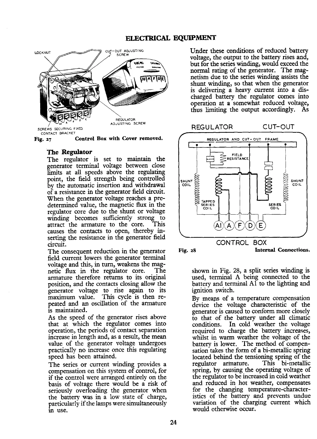
LOCKNUT CUT-OUT ADJUSTING
SCREW
CONTACT BRACKET
Fig.
27
Control Box
with
Cover removed.
The
Regulator
The regulator is set to maintain the
generator terminal voltage between close
limits at all speeds above the regulating
point, the field strength being controlled
by the automatic insertion and withdrawal
of a resistance in the generator field circuit.
When the generator voltage reaches a pre-
determined
value, the magnetic flux in the
regulator core due to the shunt or voltage
winding becomes sufficiently strong to
attract the armature to the core. This
causes the contacts to open, thereby in-
serting the resistance in the generator field
circuit.
The consequent reduction in the generator
field current lowers the generator terminal
voltage and this, in turn, weakens the mag-
netic flux
in
the regulator core. The
armature therefore returns to its original
position, and the contacts closing allow the
generator voltage to rise again to its
maximum
value. This cycle is then re-
peated and
an
oscillation of the armature
is maintained.
As the speed of the generator rises above
that at which the regulator comes into
operation, the periods of contact separation
increase in length and, as a result, the
mean
value of the generator voltage undergoes
practically no increase once this regulating
speed has been attained.
The series or current winding provides a
compensation on this system of control, for
if the control were arranged entirely on the
basis of voltage there would be a risk of
seriously overloading the generator when
the battery was in a low state of charge,
particularly if the lamps were simultaneously
m
use.
Under these conditions of reduced battery
voltage, the output to the battery rises and,
but for the series winding, would exceed the
normal rating of the generator. The mag-
netism due to the series winding assists the
shunt winding, so that when the generator
is delivering a heavy current into a dis-
charged battery the regulator comes into
operation at a somewhat reduced voltage,
thus limiting the output
accordmgly. As
REGULATOR
CUT-OUT
T
\
/
REGULATOR AND CUT-OUT FRAME
\
CONTROL
BOX
Fig.
28
Internal Connections.
shown in Fig.
28,
a split series winding is
used, terminal
A
being connected to the
battery and terminal A1 to the lighting and
ignition switch.
By meaps of a temperature compensation
device the voltage characteristic of the
generator is caused to conform more closely
to that of the battery under
all
climatic
conditions. In cold weather the voltage
required to charge the battery increases,
whilst in warm weather the voltage of the
battery is lower. The method of compen-
sation takes the form of a bi-metallic spring
located behind the tensioning spring of the
regulator armature. This
bimetallic
spring, by causing the operating voltage of
the regulator to be increased in cold weather
and reduced in hot weather, compensates
for the changing
temperature-character-
istics of the battery and prevents undue
variation of the charging current which
would otherwise occur.
 Loading...


