ELECTRICAL EQUIPMENT
removed, these settings should not
be tampered with. If, however,
the armature has been removed,
the regulator
will
have to be reset.
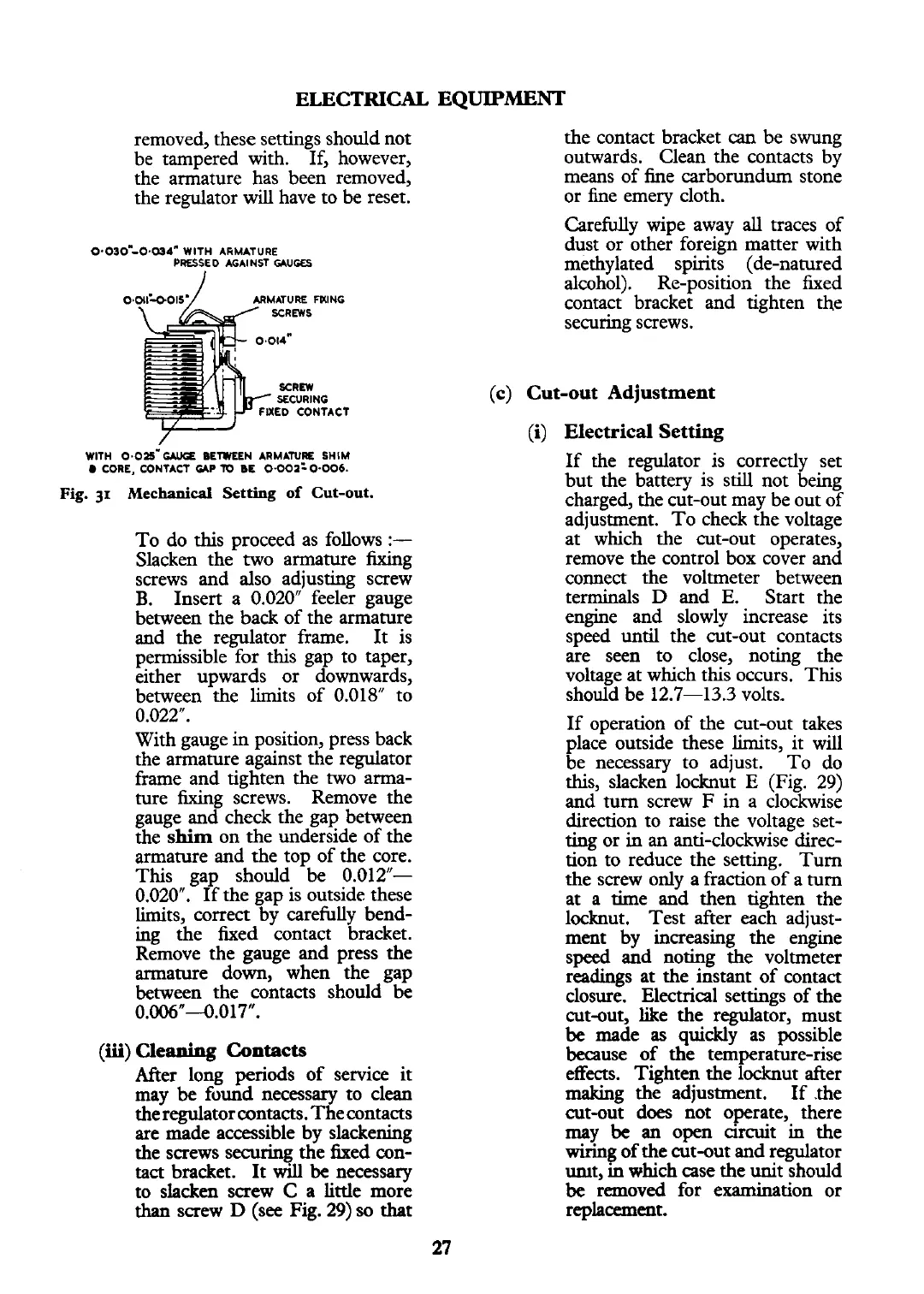
0.030-0.(~4^ WlTH ARMATURE
PRESSED AGAINST
C*UGES
ARMATURE mlNG
UED CONTACT
WlTH 0.025-- BETWEEN ARMATURE SHIM
CORE, CONTACT
UP
X)
BE 0.002=0.006.
Fig.
31
Mechanical
Setting
of Cut-out.
To do this proceed as follows
:-
Slacken the two armature fixing
screws and also adjusting screw
B.
Insert a 0.020" feeler gauge
between the back of the armature
and the regulator frame.
It is
permissible for this gap to taper,
either upwards or downwards,
between the limits of 0.018" to
0.022.
With gauge in position, press back
the armature against the regulator
frame and tighten the two arma-
ture fixing screws. Remove the
gauge and check the gap between
the
shim
on the underside of the
armature and the top of the core.
This gap should be 0.012"-
0.020". If the gap is outside these
limits, correct by carefully bend-
ing the fixed contact bracket.
Remove the gauge and press the
armature down, when the gap
between the contacts should be
0.006"--0.017".
(M)
Cleaning Contacts
After long periods of service it
may
be
found necessary to clean
the regulator contacts. The contacts
are made accessible by slackening
the screws securing the fixed mn-
tact bracket. It
will
be
necessary
to slacken screw
C
a little more
than
screw
D
(see Fig.
29)
so
that
the contact bracket
can
be swung
outwards. Clean the contacts by
means of
he carborundum stone
or fine emery cloth.
Carefully wipe away
all
traces of
dust or other foreign matter with
methylated spirits (de-natured
alcohol). Re-position the fixed
contact bracket and tighten the
securing screws.
(c) Cut-out Adjustment
(i)
Electrical Setting
If the regulator is correctly set
but the battery is still not being
charged, the cut-out may be out of
adjustment. To check the voltage
at which the cut-out operates,
remove the control box cover and
connect the voltmeter between
terminals
D
and
E.
Start the
engine and slowly increase its
speed until the cut-out contacts
are seen to close, noting the
voltage at which this occurs. This
should be
12.7-13.3
volts.
If operation of the cut-out takes
place outside these limits, it
will
be necessary to adjust. To do
this, slacken locknut
E
(Fig. 29)
and turn screw
F
in a clockwise
direction to raise the voltage set-
ting or in an anti-clockwise direc-
tion to reduce the setting. Turn
the screw only a fraction of a turn
at a time and then tighten the
locknut. Test after each adjust-
ment by increasing the engine
speed and noting the voltmeter
readings at the instant of contact
closure.
Electrical
settings of the
cut-out, like the regulator, must
be
made
as
quickly as possible
because of the temperature-rise
effects. Tighten the locknut after
making the adjustment. If .the
cut-out
does
not operate, there
may
be
an
open circuit in the
wiring
of the cut-out and regulator
mt,
in
which case the unit should
be
removed for examination or
replacement.
 Loading...


