ELECTRICAL
EQUIPMENT
(ii) Mechanical Setting
If for any reason the cut-out
armature has to be removed from
the frame, care must be taken to
obtain the correct air-gap settings
on re-assembly (see Fig. 31). These
can
be obtained as follows
:-
Slacken the two armature furing
screws, adjusting screw
F
and the
screw securing the fixed contact.
Insert a 0.014 gauge between the
back of the armature and the cut-
out frame. (The air gap between
the core face and the armature
shim should now measure 0.011"
-4.015". If it does not,
fit
a new
armature assembly.) Press the
armature back against the gauge
and tighten the armature fixing
screws. With the gauge still in
position, set the gap between the
armature and the stop plate arm
to 0.030"---0.034" by carefully
bending the stop plate arm. Re-
move the gauge and tighten the
screw securing the fixed contact.
Insert a 0.025" gauge between the
core face and the armature. Press
the armature down on to the
~ ~
gauge. The gap between the con-
tacts should now measure 0.002"
to 0.006" and the drop-off voltage
should be between the limits
given
in
Para.
2
(b). If necessary,
adjust the gap by carefully
bending the fixed contact bracket.
(iii) Cleaning Contacts
If the cut-out contacts appear
rough or burnt, place a strip of
fine glass paper between the con-
tacts-then, with the contacts
closed by hand, draw the paper
through. This should be done
two or three times with the rough
side towards each contact. Wipe
away all dust or other foreign
matter, using a clean
fluffless cloth
moistened with methylated spirits
(de-natured alcohol).
Do not use emery cloth or a car-
borundum stone for cleaning cut-
out contacts.
WINDSCREEN WIPER CRTI~
I.
GENERAL
Normally the windscreen wiper will not
require any servicing apart from the oc-
casional renewal of the rubber blades.
In the event of irregular working, first check
for loose connections, chafed insulation,
discharged battery, etc., before removing
the gearbox or commutator covers.
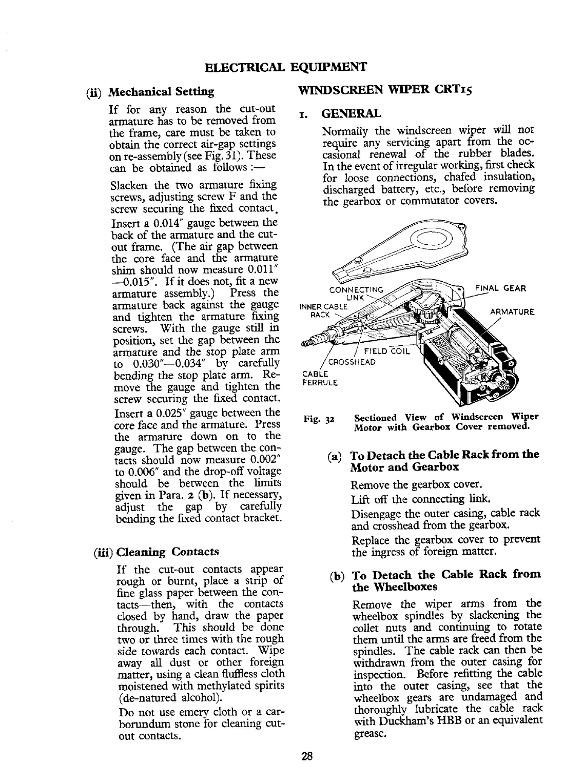
Fig.
32
Sectioned View of Windscreen Wiper
Motor with Gearbox Cover removed.
(a) To Detach
the
Cable Rack from
the
Motor and Gearbox
Remove the gearbox cover.
Lift
off the connecting
link.
Disengage the outer casing, cable rack
and crosshead from the gearbox.
Replace the gearbox cover to prevent
the ingress of foreign matter.
(b) To Detach the Cable Rack from
the Wheelboxes
Remove the wiper arms from the
wheelbox spindles by slackening the
collet nuts and continuing to rotate
them
until
the arms are freed from the
spindles. The cable rack
can
then be
withdrawn from the outer casing for
inspection. Before refitting the cable
into the outer casing, see that the
wheelbox gears are undamaged and
thoroughly lubricate the cable
rack
with Duckham's HBB or an equivalent
grease.
 Loading...


