ELECTRICAL
EQUIPMENT
Withdraw the cables from control
box terminals
A
and
A1
and
connect these cables together.
Connect the negative lead of the
voltmeter to control box terminal
D,
and connect .the other lead to
terminal
E.
Slowly increase the speed of the
engine until the voltmeter needle
"
flicks
"
and then steadies. This
should occur at a voltmeter read-
ing between the appropriate limits
given in Para.
2
(a)
according to
the ambient temperature.
If the voltage at which the reading
becomes steady occurs outside
these limits, the regulator must
be adjusted.
Shut off the engine and remove
the control box cover.
Slacken the
locknut of the voltage
adjusting screw (see Fig.
38)
and
turn
the screw
in
a clockwise
direction to raise the setting or in
an
anti-clockwise direction to
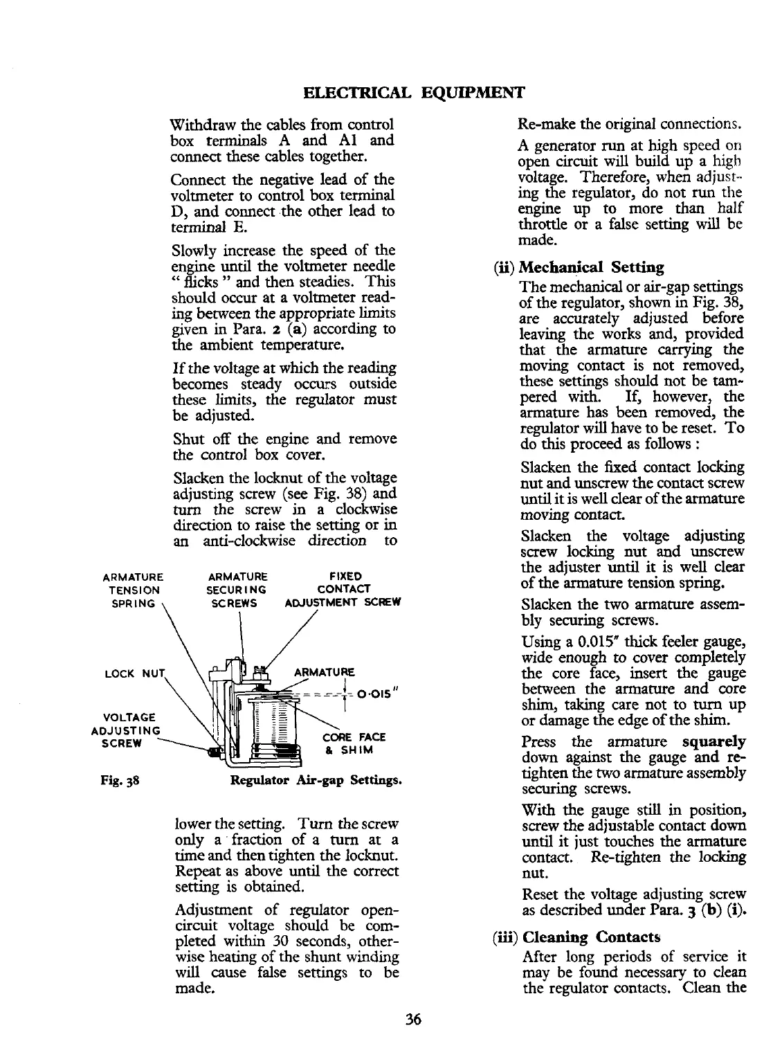
ARMATURE ARMATURE FIXED
TENSION
SECURING CONTACT
SPRING
\
SCREWS ADJUSTMENT
SCREW
VOLTAGE
ADJUSTING
Fig.
38
Regulator Air-gap Settings.
lower the setting.
Turn the screw
only a. fraction of a
turn
at a
time
and then tighten the locknut.
Repeat as above until the correct
setting is obtained.
Adjustment of regulator open-
circuit voltage should be com-
pleted within
30
seconds, other-
wise heating of the shunt winding
will cause false settings to be
made.
Re-make the original connections.
A
generator
run
at high speed on
open circuit will build up a
high
voltage. Therefore, when adjust-
ing the regulator, do not
run
the
engine up to more than half
throttle or a false setting will be
made.
(ii)
Mechanical Setting
The mechanical or air-gap settings
of the regulator, shown in Fig.
38,
are accurately adjusted before
leaving the works and, p!ovided
that the armature carrymg the
moving contact is not removed,
these settings should not be
tarn-
pered with. If, however, the
armature has been removed, the
regulator will have to be reset. To
do this proceed as follows
:
Slacken the fixed contact locking
nut and unscrew the contact screw
until it is well clear of the armature
moving contact.
Slacken the voltage adjusting
screw locking nut and unscrew
the adjuster until
it
is well clear
of the armature tension spring.
Slacken the two armature assem-
bly securing screws.
Using a
0.015"
thick feeler gauge,
wide enough to cover completely
the core face, insert the gauge
between the armature and core
shim, taking care not to
turn
up
or damage the edge of the shim.
Press the armature
squarely
down against the gauge and re-
tighten the two armature assembly
securing screws.
With the gauge still in position,
screw the adjustable contact down
until it just touches the armature
contact. Re-tighten the locking
nut.
Reset the voltage adjusting screw
as described under
Para.
3
(b)
(i).
(iii)
Cleaning Contacts
After long periods of service it
may be found necessary to clean
the regulator contacts. Clean the
 Loading...


