ELECTRICAL
contacts by means of fine car-
borundum stone or fine emery
cloth.
Carefully wipe away all traces of
dust or other foreign matter with
methylated spirits (de
-
natured
alcohol).
(c) Cut-out Adjustment
(i)
Electrical Setting
If the regulator is correctly set
but the battery is still not being
charged, the cut-out may be out
of adjustment. To check the
voltage at which the cut-out oper-
ates, remove the control box cover
and connect the voltmeter be-
tween terminals
D
and
E.
Start
the engine and slowly increase its
speed until the cut-out contacts
are seen to close, noting the
voltage at which this occurs. This
should be
12.7-13.3
volts.
If operation of the cut-out takes
place outside these limits, it will
be necessary to adjust. To do
this, slacken the locknut securing
the cut-out adjusting screw (see
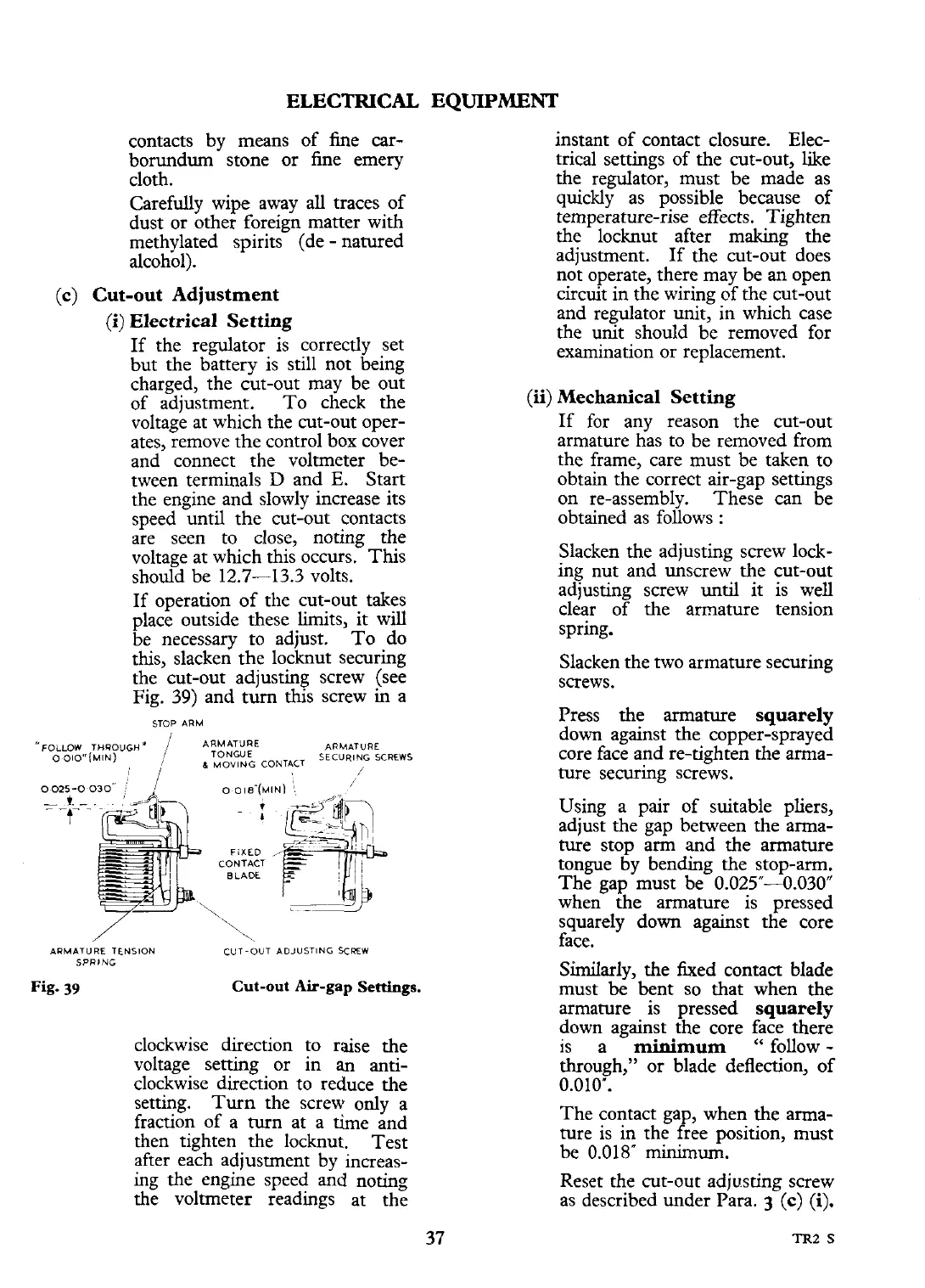
Fig.
39)
and
turn
this screw
in
a
STOP ARM
o
OI~'(MIN\
/
CONTACT
BLADE
--
-p
ARMATURE TENSION CUT-OUT ADJUSTING
SCREW
SPRING
Fig.
39
Cut-out
Air-gap
Settings.
clockwise direction to raise the
voltage setting or in
an
anti-
clockwise direction to reduce the
setting. Turn the screw only a
fraction of a turn at a time and
then tighten the
locknut. Test
after each adjustment by inaeas-
ing the engine speed
and
noting
the voltmeter readings at the
EQUIPMENT
instant of contact closure. Elec-
trical settings of the cut-out, like
the regulator, must be made as
quickly as possible because of
temperature-rise effects. Tighten
the locknut after making the
adjustment. If the cut-out does
not operate, there may be an open
circuit in the wiring of the cut-out
and regulator unit, in which case
the unit should be removed for
examination or replacement.
(ii)
Mechanical Setting
If for any reason the cut-out
armature has to be removed from
the frame, care must be taken to
obtain the correct
air-gap settings
on re-assembly. These can be
obtained as follows
:
Slacken the adjusting screw lock-
ing nut and unscrew the cut-out
adjusting screw until it is well
clear of the armature tension
spring.
Slacken the two armature securing
screws.
Press the armature
squarely
down against the copper-sprayed
core face and re-tighten the arma-
ture securing screws.
Using a pair of suitable pliers,
adjust the gap between the arma-
ture stop arm and the armature
tongue by bending the stop-arm.
The gap must be 0.025"--0.030"
when the armature is pressed
squarely down against the core
face.
Similarly, the fixed contact blade
must be bent so that when the
armature is pressed
squarely
down against the core face there
is a
minimum
"
follow
-
through," or blade deflection, of
0.010".
The contact gap, when the arma-
ture is
in
the free position, must
be 0.018" minimum.
Reset the cut-out adjusting screw
as described under Para.
3
(c)
(i).
 Loading...


