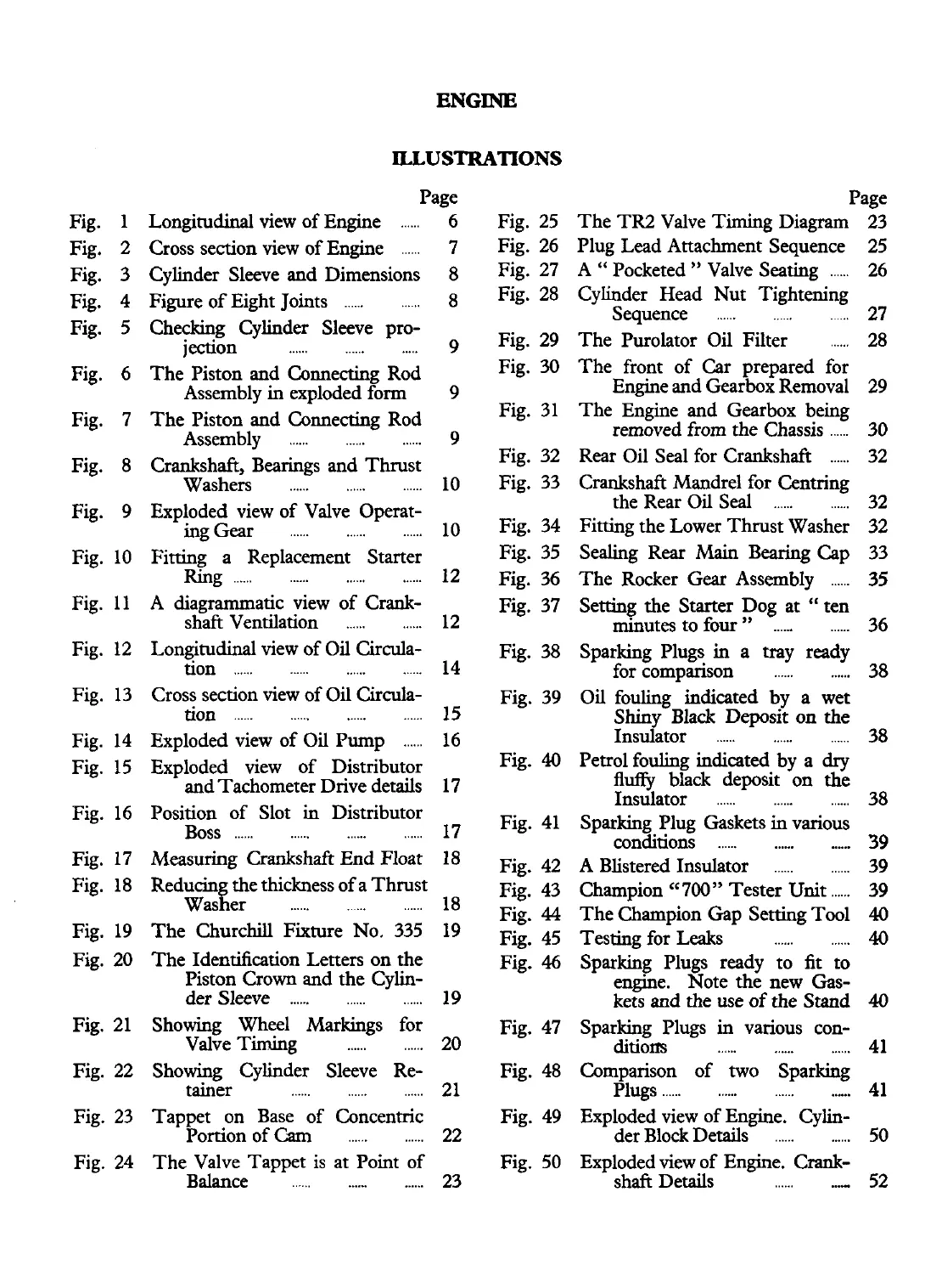
ILLUSTRATIONS
Fig
.
1
Fig
.
2
Fig
.
3
Fig
.
4
Fig
.
5
Fig
.
6
Fig
.
7
Fig
.
8
Fig
.
9
Fig
.
10
Fig
.
11
Fig
.
12
Fig
.
13
Fig
.
14
Fig
.
15
Fig
.
16
Fig
.
17
Fig
.
18
Fig
.
19
Fig
.
20
Fig
.
21
Fig
.
22
Fig
.
23
Fig
.
24
Page
Longitudinal view of Engine
......
6 Fig
.
25
.
......
Cross section view of Engine 7 Fig 26
Cylinder Sleeve and Dimensions 8 Fig
.
27
Figure of Eight Joints
............
8 Fig
.
28
Checking Cylinder Sleeve pro-
j
ection
......
......
.....
The Piston and Connecting Rod
Assembly in exploded form
The Piston and Connecting Rod
Assembly
......
......
......
Crankshaft. Bearings and Thrust
......
Washers
......
......
Exploded view of Valve Operat-
ingGear
......
......
......
Fitting a Replacement Starter
......
Ring
............
......
A diagrammatic view of Crank-
......
shaft Ventilation
......
Longitudinal view of Oil Circula-
......
tion
............
......
Cross section view of Oil Circula-
tion
............
......
......
......
Exploded view of Oil Pump
Exploded view of Distributor
and Tachometer Drive details
Fig
.
29
Fig
.
U)
Fig
.
31
Fig
.
32
Fig
.
33
Fig
.
34
Fig
.
35
Fig
.
36
Fig
.
37
Fig
.
38
Fig
.
39
Fig
.
40
Position of Slot in Distributor
Boss
............
......
......
17
Fig
.
41
Measuring Crankshaft End Float 18 ~i~
.
42
"
Reducing the thickness of a Thrust
Fig
.
43
Washer
......
...... ......
18
Fig
.
44
The Churchill Fixture No
.
335 19
~i~
.
45
The Identification Letters on the
FG
.
46
Piston Crown and the Cylin-
............
der Sleeve
......
19
Showing Wheel Markings for Fig
.
47
Valve Timing
......
......
20
Showing Cylinder Sleeve Re- Fig
.
48
tainer
......
......
......
21
Tappet on Base of Concentric
Fig
.
49
PomonofCam
......
......
22
Page
The TR2 Valve Timing Diagram 23
Plug Lead Attachment Sequence 25
A
"
Pocketed
"
Valve Seating
......
26
Cylinder Head Nut Tightening
Sequence
......
......
...
27
The Purolator Oil Filter
......
28
The front of Car prepared for
Engine and Gearbox Removal 29
The Engine and Gearbox being
removed from the Chassis
......
30
Rear Oil Seal for Crankshaft
......
32
Crankshaft Mandrel for Centring
the Rear Oil Seal
............
32
Fitting the Lower Thrust Washer 32
Sealing Rear
Main
Bearing Cap 33
The Rocker Gear Assembly
......
35
Setting the Starter Dog at "ten
minutes to four
"
......
......
36
Sparking Plugs
in
a tray ready
......
for comparison
......
38
Oil fouling indicated by a wet
Shiny Black Deposit on the
Insulator
......
......
......
38
Petrol fouling indicated by a
dry
fluffy
black deposit on the
Insulator
......
......
......
38
Sparking Plug Gaskets in various
conditions
............
......
39
A Blistered Insulator
......
......
39
Champion cc700" Tester Unit
......
39
The Champion Gap Setting Tool
40
Testing for Leaks
......
......
40
Sparking Plugs ready to fit to
engine
.
Note the new Gas-
kets and the use of the Stand
40
Sparking Plugs in various con-
ditions
......
......
......
41
Comparison of two Sparking
Plugs
............
......
...-.
41
Exploded view of Engine
.
Cylin-
......
der Block Details
......
50
The Valve Tappet is at Point of
Fig
.
50 Exploded view of Engine
.
Crank-
Balance
......
.....
......
23 shaft Details
......
...,
52
 Loading...


