FUEL SYSTEM
TO ASSEMBLE PETROL PUMP
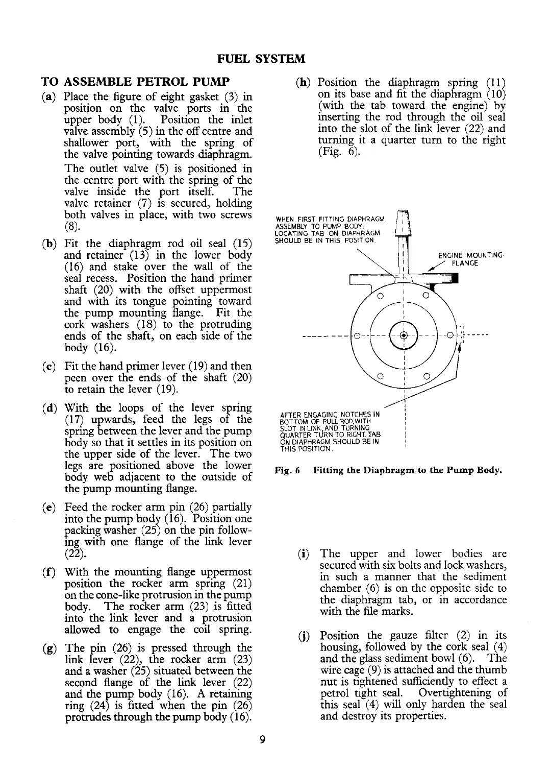
(h)
Position the diaphragm spring (11)
(a)
Place the figure of eight gasket (3) in on its base and fit the diaphragm (10)
position on the valve ports in the (with the tab toward the engine) by
upper body (1). Position the inlet inserting the rod through the oil seal
valve assembly (5) in the off centre and into the slot of the link lever (22) and
shallower port, with the spring of turning it a quarter turn to the right
the valve pointing towards diaphragm. (Fig. 6).
The outlet valve (5) is positioned in
the centre port with the spring of the
valve inside the port itself. The
valve retainer (7) is secured, holding
both valves in place, with two screws
,
,,,,
,,,,,
,,
,,,,,
,,,,
(8).
ASSEMBLY TO PUMP BODY,
LOCATING TAB ON DIAPHRAGM
(b)
Fit the diaphragm rod oil seal (15)
BE
IN
POSIT'ON.
and retainer (13) in the lower body
(16) and stake over the wall of the
seal recess.
Position the hand primer
shaft (20) with the offset uppermost
and with its tongue pointing toward
the pump mounting flange.
Fit the
cork washers (18) to the protruding
ends of the shaft, on each side of the
body (16).
(c) Fit the hand primer lever (19) and then
peen over the ends of the shaft (20)
to retain the lever (19).
/'?
(d)
With
the
loops of the lever spring
AFTER
ENCAGIN'
NOTCHES
IN
j
(17) upwards, feed the legs of the
BOTTOM
OF
PVLLROD.WITH
spring between the lever and the pump
TAB
1
body so that it settles in its position on
?;,F;;gpT:;;,sHOULD BE
IN
;
the upper side of the lever.
The two
legs
are
positioned above
the
lower
Fig.
6
Fitting the
Diaphragm
to
the
Pump
Body.
body web adjacent to the outside of
the pump mounting flange.
(e)
Feed the rocker
arm
pin (26) partially
into the pump body (16). Position one
packing washer (25) on the pin follow-
ing with one flange of the
link
lever
(22).
(f) With the mounting flange uppermost
position the rocker arm spring (21)
on the cone-like protrusion in the pump
body. The rocker arm (23) is fitted
into the
link lever and a protrusion
allowed to engage the coil spring.
(g)
The pin (26) is pressed through the
link
lever (22), the rocker arm (23)
and a washer (25) situated between the
second flange of the
link
lever (22)
and the pump body (16).
A
retaining
ring
(24)
is fitted when the pin (26)
protrudes through the pump body (16).
9
(i)
The upper and lower bodies are
secured with six bolts and lock washers,
in such a manner that the sediment
chamber (6) is on the opposite side to
the diaphragm tab, or in accordance
with the file marks.
(j)
Position the gauze filter (2) in its
housing, followed by the cork seal (4)
and the glass sediment bowl (6). The
wire cage (9) is attached and the thumb
nut is tightened sufficiently to effect a
petrol tight seal. Overtightening of
this seal (4) will only harden the seal
and destroy its properties.
 Loading...


