FUEL
SYSTEM
NOTATION FOR
Fig.
5.
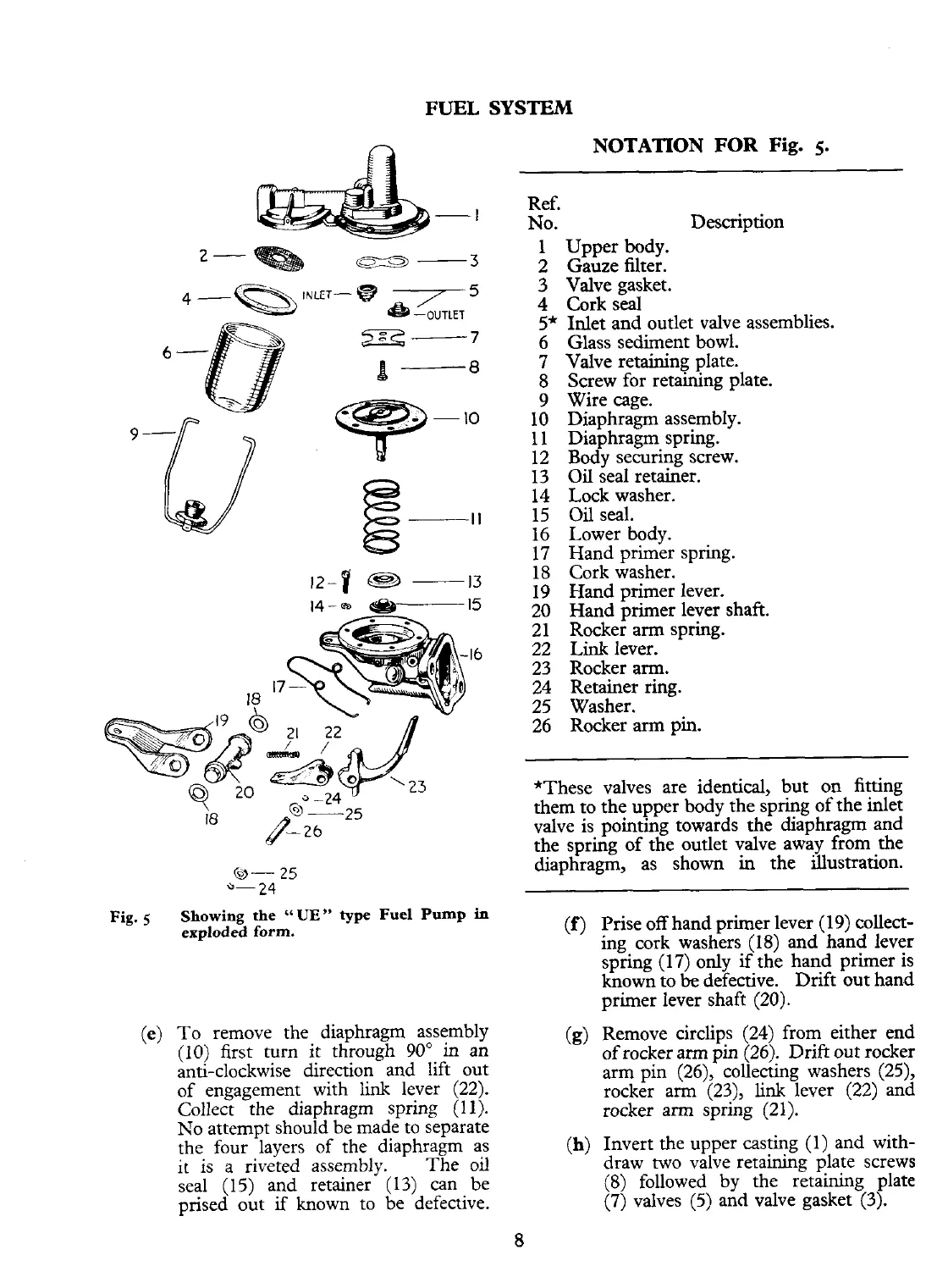
Fig.
5
Showing the
"UE"
type
Fuel
Pump
in
exploded
form.
(e)
To remove the diaphragm assembly
(10) first turn it through 90" in an
anti-clockwise direction and lift out
of engagement with link lever (22).
Collect the diaphragm spring
(1 1).
No attempt should be made to separate
the four layers of the diaphragm as
it is a riveted assembly. The oil
seal (15) and retainer (13) can be
prised out
if
known to be defective.
Ref.
No. Description
1 Upper body.
2
Gauze filter.
3 Valve gasket.
4
Cork seal
S*
Inlet and outlet valve assemblies.
6 Glass sediment bowl.
7 Valve retaining plate.
8
Screw for retaining plate.
9 Wire cage.
10 Diaphragm assembly.
11 Diaphragm spring.
12 Body securing screw.
13
Oil
seal retainer.
14 Lock washer.
15
Oil
seal.
16 Lower body.
17 Hand primer spring.
18
Cork washer.
19 Hand primer lever.
20 Hand primer lever shaft.
21 Rocker arm spring.
22
Link
lever.
23 Rocker arm.
24 Retainer ring.
25 Washer.
26 Rocker arm pin.
*These valves are identical, but on fitting
them to the upper body the spring of the inlet
valve is pointing towards the diaphragm and
the spring of the outlet valve away from the
diaphragm, as shown in the illustration.
(f)
Prise off hand primer lever (19) collect-
ing cork washers (18) and hand lever
spring (17) only
if
the hand primer is
known to
be
defective. Drift out hand
primer Iever shaft (20).
(g)
Remove circlips (24) from either end
of rocker arm pin (26). Drift out rocker
arm pin
(26), collecting washers (25),
rocker arm (23),
link
lever
(22)
and
rocker arm spring (21).
(h)
Invert the upper casting (1) and with-
draw two valve retaining plate screws
(8)
followed by the retaining plate
(7) valves
(5)
and valve gasket (3).