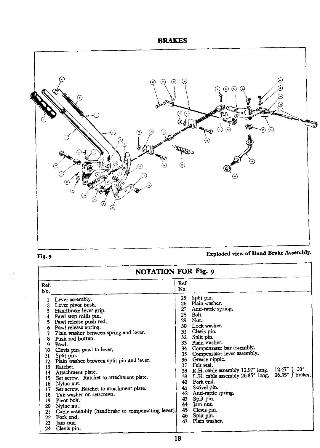
BRAKES
I
i
Fig.
9
Exploded
view
of
Hand
Brake
Assembly.
NOTATION FOR Fig.
g
l
Ref.
No.
1
Lever assembly.
2
Lever pivot bush.
3
Handbrake lever grip.
4
Pawl stop mills pin.
5
Pawl release push rod.
6
Pawl Aease spring.
7
Plain washer between spring and lever.
8
Push
rod button.
l
9
Pawl.
10
Clevis pin, pawl to lever.
11
Split pin.
12
Plain washer
between
split pin and lever.
13
Ratchet.
14
Attachment plate.
15 Set screw. Ratchet to attachment plate.
16
Nyloc nut.
17
Set
screw.
Ratchet to attachment plate.
18
Tab washer on setscrews.
19
Pivot bolt.
1
20
~~loc nut.
l
21
Cable assembly (handbrake to compensating lever).
22
Fork end.
23
Jam
nut.
24
Clevis pin.
18
Ref.
No.
25
Split pin.
26
Plain washer.
27
Anti-rattle spring.
28
Bolt
29
Nut.
30
Lock washer.
31
Clevis pin.
32
Split pin.
33
Plain washer.
34
Compensator
bar
assembly.
35
Compensator lever assembly.
36
Grease nipple.
37
Felt seal.
38
R.H.
cable assembly
12.97"
long.
12.47" 10"
39
L.H.
able swmbly
26.85"
long.
26.35'
1
brake
40
Fork end.
41
Swivel pin.
42
Anti-rattle spring.
43 Split pin.
44
Jam
nut.
45
clevispin.
46
Split pin.
47
Plain washa.