ENGINE
I.
GENERAL
DESCRIPTION
(Figs.
I
and
2)
The Engine
has four cylinders and
the overhead valves are push rod
operated, the 83
mm.
bore and 92
mm.
stroke give a capacity of 1,991 cubic
centimetres. The compression is 8.5
to 1.
A low compression kit (see page 27)
is available and reduces the com-
pression ratio to 7.5 to 1.
The Cylinder
Block
is an integral
casting in cast iron, the abutments for
the cylinder sleeves, the three rear
camshaft bearings and the crankshaft
bearing housings are machined in a
single unit. The main bearing housings
are line bore machined
;
the bearing
caps are not interchangeable and are
stamped together with the casting to
assist identification.
After Engine No.
9095E four Vander-
vel bi-metal bearings were fitted
to accommodate the camshaft.
A
recognition feature of engines so fitted
with these bearings will be that three
setscrews retaining the three rearmost
bearings will clearly be seen on the left-
hand side of the cylinder block. See
TR3 Supplement Engine Section
"B".
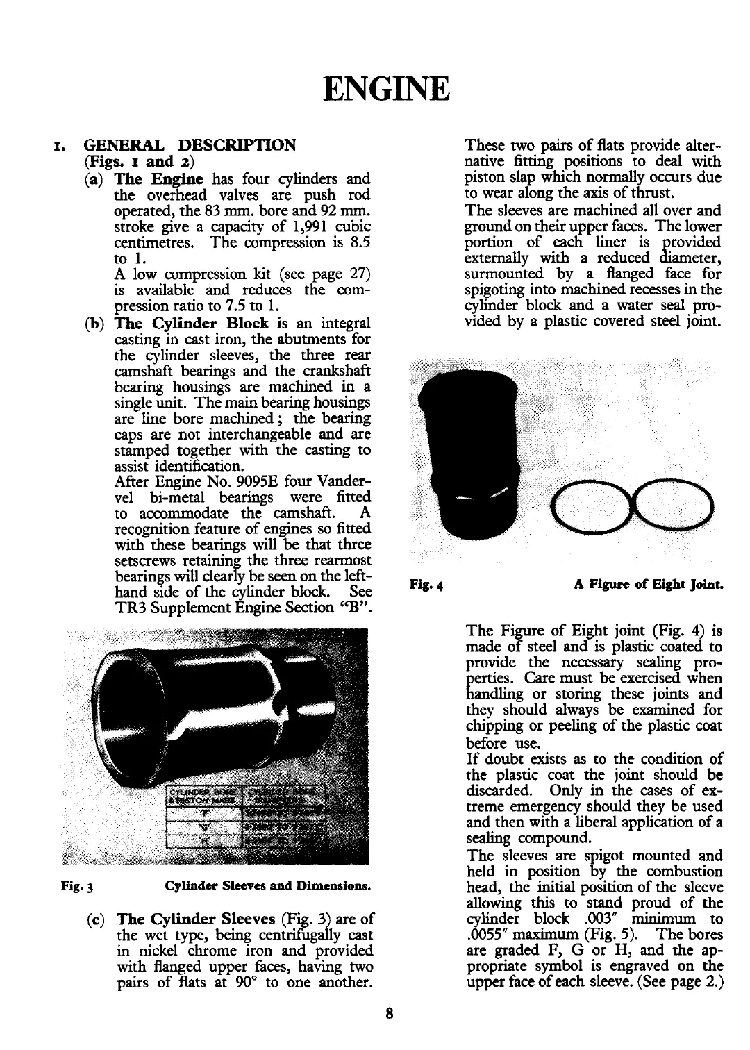
Fig.
3
Cylinder
Sleeves
and
Dimensions.
(c)
The Cylinder Sleeves
(Fig. 3) are of
the wet type, being centrifugally cast
in nickel chrome iron and provided
with flanged upper faces, having two
pairs of
fits at
90"
to one another.
These two pairs of flats provide alter-
native fitting positions to deal with
piston slap which normally occurs due
to wear along the axis of thrust.
The sleeves are machined
all
over and
ground on their upper faces. The lower
portion of each liner is provided
externally with a reduced diameter,
surmounted by a flanged face for
spigoting into machined recesses in the
cylinder block and a water seal pro-
vided by a plastic covered steel joint.
A
Figure
of
Eight
Joint.
The Figure of Eight joint (Fig.
4)
is
made of steel and is plastic coated to
provide the necessary sealing pro-
perties. Care must
be
exercised when
handling or storing these joints and
they should always be examined for
chipping or peeling of the plastic coat
before use.
If doubt exists as to the condition of
the plastic coat the joint should be
discarded. Only
in
the cases of ex-
treme emergency should they be used
and then with a liberal application of a
sealing compound.
The sleeves are spigot mounted and
held in position by the combustion
head, the initial position of the sleeve
allowing this to stand proud of the
cylinder block
.003"
minimum
to
.0055" maximum (Fig. 5).
The bores
are graded F,
G
or
H,
and the ap-
profiate symbol is engraved on the
upper face of each sleeve. (See page 2.)
 Loading...


