ENGINE
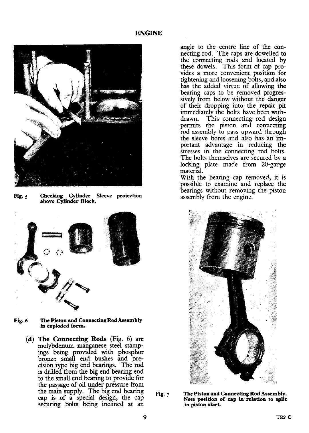
Fig.
5
Checking
Cylinder Sleeve projection
above Cylinder Block.
Fig.
6
The Piston and
Connecting
Rod Assembly
in
exploded form.
(d)
The
Connecting
Rods
(Fig.
6)
are
molybdenum manganese steel stamp-
ing~ being provided with phosphor
bronze small end bushes and pre-
cision type big end bearings. The rod
is drilled from the big end bearing end
to the small end bearing to provide for
the passage of oil under pressure
from
the main supply. The big end bearing
cap is of a special design, the cap
securing bolts being inclined at
an
angle to the centre line of the con-
necting rod. The caps are dowelled to
the
connecting rods and located by
these dowels. This form of cap pro-
vides
a
more convenient position for
tightening and loosening bolts,
and
also
has the added virtue of allowing the
bearing caps to be removed progres-
sively from below without the danger
of their dropping into the repair pit
immediately the bolts have been with-
drawn. This connecting rod design
permits the piston and connecting
rod assembly to pass upward through
the sleeve bores and also has an
im-
portant advantage in reducing the
stresses in the connecting rod bolts.
The bolts themselves are secured by a
locking plate made from 20-gauge
material.
With the bearing cap removed, it is
possible to examine and replace the
bearings without removing
the piston
assembly from the engine.
The
Piston and
Co~ectiag
Rod Assembly.
Note position of cap
h
relation to split
in
piston skirt.