ENGINE
(e) Aeroflex Compensating Pistons
(Fig
6)
are employed, which are made
from
a
special aluminium alloy and
each provided with two compression
rings and one oil scraper ring.
The pistons are graded F,
G
or
H
(dimensions on page
2)
and this symbol
is stamped on the crowns. The piston
skirt has a
h"
slot on the non-pressure
side and is fitted to the connecting rod
so that this slot is away from the point
of maximum thrust, Fig.
7
(facing the
camshaft side of the engine).
3g.8
CmnbhPtt,
Benring
and
Thrust
Washers.
(f)
The Crankshaft
(Fig. 8) is forged
from molybdenum manganese steel,
being provided with balance weights
which are
an
integral part of the crank-
shaft throws, adjacent to the three main
bearings.
This shafl is accommodated in three
precision type white metal steel back
bearings, which are housed in the
cylinder block, being secured in
position by bearing caps and two bolts
and spring washers per journal. Crank-
shaft thrust is taken by steel white
metal covered washers which are fitted
in two halves on either side of the
centre
main
bearing housing, being
located circumferentially by means of
projections on the lower half of each
pair
of washers.
Jn the case of extreme necessity and
knowing that the crankshaft is in good
condition, it is possible to change the
main
bearings
without first removing
the engine from the chassis. It is
essential however that extreme care
be taken when replacing the front
and rear oil seals.
This operation is
described on page
32
and
33.
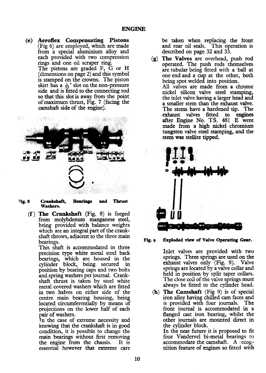
(g) The Valves
are overhead, push rod
operated. The push rods themselves
are tubular being fitted with a ball at
one end and a cup at the other, both
being spot welded into position.
All valves are made from a chrome
nickel silicon valve steel stamping,
the inlet valve having
a
larger head and
a smaller stem
than
the exhaust valve.
The stems have a hardened tip. The
exhaust valves fitted
to
-engines
after Engine No.
TS.
481
E
were
made from a
high
nickel chromium
tungsten valve steel stamping, and the
stem
was
stellite tipped.
Fig.
g
Exploded
view
of
Valve
Operating
Gear.
Inlet valves are provided with two
springs. Three springs are used on the
exhaust valves only (Fig.
9).
Valve
springs are located by a valve collar and
held in position by split taper collars.
The close
c02 of the valve springs must
always be fitted to the cylinder head.
(h)
The Camshaft
(Fig
9)
is of special
iron alloy having chilled
cam
faces and
is provided
with
four journals. The
front journal is accommodated
in
a
flanged cast iron bearing, whilst the
other journals are mounted
direct
in
the cylinder block.
In the near future it is proposed to fit
four
Vandervel bi-metal bearings
to
accommodate the camshaft. A *ecog-
nition feature of engines so fitted with
 Loading...


