ENGINE
6.
PISTON ASSEMBLY AND
CYLPN-
The importance of using cylinder sleeve
DER SLEEVES
retainers to prevent relative movement of
The piston and cylinder bore dimensions
these parts is stressed.
are given on vage
2.
As indicated in this
list if tolera&i and limits, three sizes of
pistons are used in conjunction with suitable
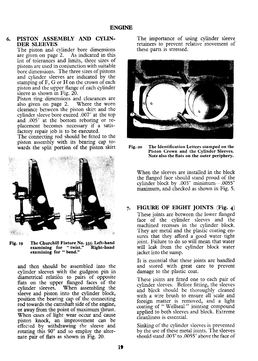
bore dimensions. The three sizes of pistons
and cylinder sleeves are indicated by the
stamping of
F,
G
or
H
on the crown of each
piston and the upper flange of each cylinder
sleeve as shown in Fig.
20.
Piston ring dimensions and clearances are
also given on page
2.
Where the worn
clearance between the piston skirt and the
cylinder sleeve bore exceed
.007" at the top
and
.005"
at the bottom reboring or re-
placement becomes necessary if a satis-
factory repair job is to be executed.
The connecting rod should be fitted to the
piston assembly with its bearing cap to-
wards the split portion of the piston skirt
Fig.
19
The Churchill Fixture No.
335.
Left-hand
examining for
"
twist." Right-hand
examining for
"
bend."
and then should be assembled into the
cylinder sleeves with the gudgeon pin in
diametrical relatibr, to pairs of opposite
flats on the upper flanged faces of the
cylinder sleeves. When assembling the
sleeve and piston into the cylinder block,
position the bearing cap of the connecting
rod towards the
camshaft side of the engine,
or away from the point of
maximum
thrust.
When cases of light wear occur andcause
piston knock, an improvement can be
effecred by withdrawing the sleeve and
rotating this
90"
and so employ the alter-
nate pair
of
flats
as shown_
in
Fig.
2C).
Fig..zo
The Identification Letters stamped on the
Piston Crown and the Cylinder Sleeves.
Note also the flats on the outer periphery.
When the sleeves are installed in the block
the flanged face should stand proud of the
cylinder block by
.003"
minimum^--.0055"
maximum, and checked as shown in Fig.
5.
7.
FIGURE
OF
EIGHT JOINTS
(Fig.
4)
These joints are between the lower flanged
face of the cylinder sleeves and the
machined recesses in the cylinder block.
They are metal and the plastic coating en-
sures that they afford a good water tight
joint. Failure to do so will mean that water
will leak from the cylinder block water
jacket into the sump.
It is essential that these joints are handled
and stored with great care to prevent
damage to the plastic coat.
These joints are fitted one to each pair of'
cylinder sleeves. Before fitting, the sleeves
and block should be thoroughly cleaned
with a wire brush to ensure all scale and
foreign matter is removed, and a light
coating of
"
Wellseal
"
jointing compound
applied to both sleeves and block. Extreme
cleanliness is essential.
Sinking of the cylinder sleeves is prevented
by the use of these metal joints. The sleeves
shodd
stand
.003"
to
.0055"
above the
face
of
 Loading...


