ENGINE
the cylinder block and a routine check
should be made whenever the combustion
head is removed. Should the cylinder
sleeve(s) be below the specified limits new
figure of eight joints should be fitted.
8.
CAMSHAFT
AND
TIMING
GEARS
The camshaft is of cast iron, having chilled
faces for the cams and journals. With the
camshaft a cast iron flanged front bearing is
used, the other three journals making direct
contact with the cylinder block.
In the near future it is proposed to fit
four Vandervel bi-metal bearings to ac-
commodate the camshaft
A
recognition of
an engine so fitted with these bearings
will
be that three setscrews retaining the three
rearmost bearings
will
be clearly visible on
the left-hand side of the cylinder block. The
front bearing is pressed into the front
bearing sleeve.
The camshaft is driven by a double roller
silent chain which engages with a sprocket
on the crankshaft and one spigotted on the
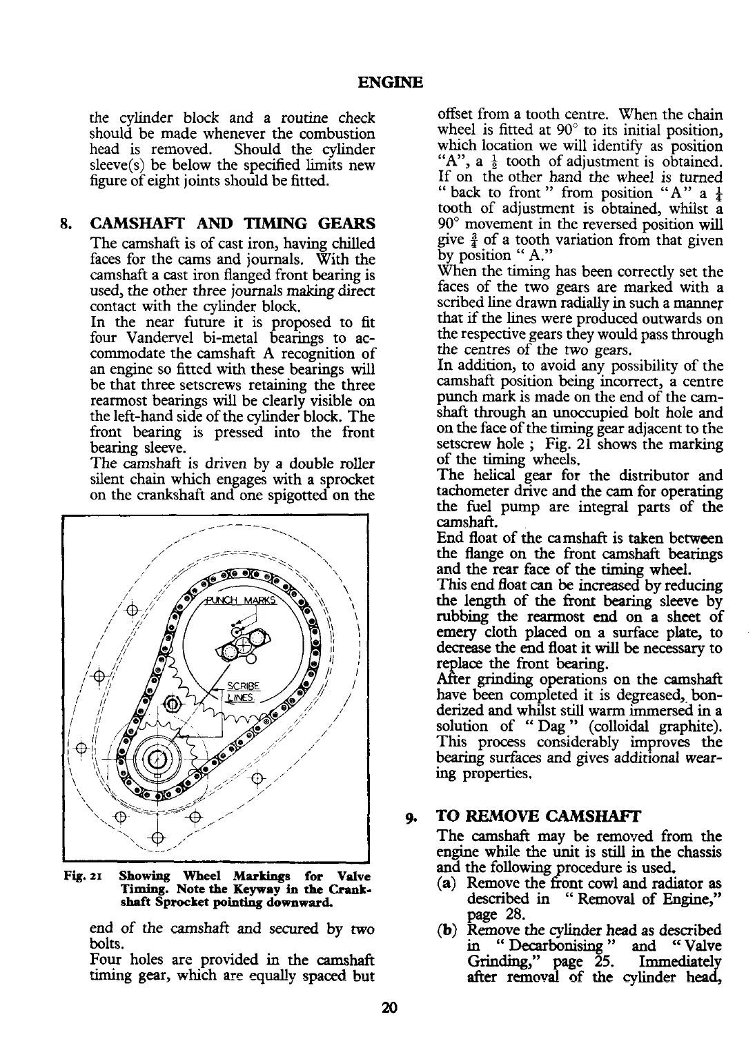
Fig.
21
Showing Wheel
Markiugs
for Valve
Timing.
Note the Keyway
in
the
Crank-
shaft Sprocket
pointing
downward
end of the camshaft and secured by two
bolts.
Four holes arc provided
in
the
camshaft
timing gear, which arc
equally
spaced hut
offset from a tooth centre. When the chain
wheel is fitted at
90"
to its initial position,
which location we will idenw as position
"
A",
a
3
tooth of adjustment is obtained.
If on the other hand the wheel is turned
"
back to front
"
from position "A" a
$
tooth of adjustment is obtained, whilst a
90"
movement in the reversed position will
give of a tooth variation from that given
by position
"
A."
When the timing has been correctly set the
faces of the two gears are marked with a
scribed line drawn radially in such a manner
that
if
the lines were produced outwards on
the respective gears they would pass through
the centres of the two gears.
In addition, to avoid any possibility of the
camshaft position being incorrect, a centre
punch mark is made on the end of the
cam-
shafi through an unoccupied bolt hole and
on the face of the
timing
gear adjacent to the
setscrew hole
;
Fig.
21
shows the marking
of the
timing
wheels.
The helical gear for the distributor and
tachometer drive and the
cam
for operating
the fuel pump are integral parts of the
camshaft.
End float of the camshaft is taken between
the flange on the front camshaft
bearings
and the rear face of the
timing
wheel.
This end float
can
be
increased by reducing
the length of the
hnt
bearing
sleeve by
rubbing
the
rearmost
end
on a sheet of
emery cloth placed on a surface plate, to
decrease the end float it will
be
necessary to
re
lace
the front
bearing.
ARer
grin-
operations on the camshaft
have
been
completed it is degreased,. bon-
derized and whilst still warm immersed
in
a
solution of
"
Dag
"
(colloidal graphite).
This process considerably improves the
bearing surfaces and gives additional wear-
ing
properties.
TO
REMOVE
CAMsm
The camshaft may
be
removed from the
engine while the unit is still
in
the chassis
and the following rocedure is used.
z
(a)
Remove the ont
cowl
and radiator as
described
in
"
Removal of
Eneine."
-
page
28.
(b)
Remove the cylinder head as described
in
"
Decarbonisine
"
and
cc
Valve
Grinding,"
page
55.
Immediate1
after
removal
of
the
cylinder
heaz
 Loading...


