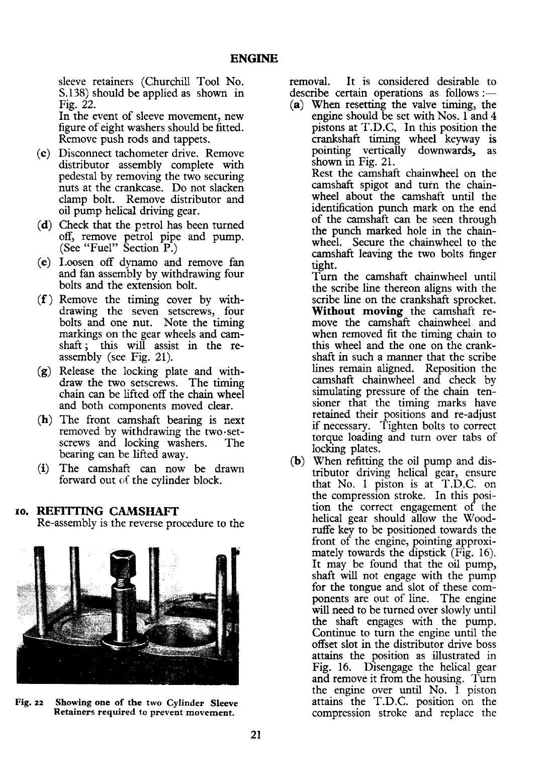
sleeve retainers (Churchill Tool No.
S.138)
should be applied as shown in
Fig. 22.
In the event of sleeve movement, new
figure of eight washers should be fitted.
Remove push rods and tappets.
Disconnect tachometer drive. Remove
distributor assembly complete with
pedestal by removing the two securing
nuts at the crankcase. Do not slacken
clamp bolt. Remove distributor and
oil pump helical driving gear.
Check that the
pctrol has been turned
off, remove petrol pipe and pump.
(See "Fuel" Section
P.)
Loosen off dynamo and remove fan
and fan assembly by withdrawing four
bolts and the extension bolt.
Remove the timing cover by with-
drawing the seven setscrews, four
bolts and one nut. Note the timing
markings on the gear wheels and cam-
shaft; this will assist in the
re-
assembly (see Fig. 21).
Release the locking plate and
with-
draw the two setscrews. The timing
chain
can
be lifted off the chain wheel
and both components moved clear.
The front camshaft bearing is next
removed by withdrawing the two-set-
screws and locking washers. The
bearing can be lifted away.
-
The camshaft
can
now be drawn
forward out
of
the cylinder block.
10.
REFITTING
CAMSHAFT
Re-assembly is the reverse procedure to the
Fig.
zz
Showing one of the two Cylinder Sleeve
Retainers required
t=
prevent movement.
removal. It is considered desirable to
describe certain operations as follows
:-
(a)
When resetting the valve timing, the
engine should be set with Nos. 1 and
4
pistons at T.D.C, In this position the
crankshaft timing wheel keyway
is
pointing vertically downwards, as
shown in Fig. 21.
Rest the camshaft chainwheel on the
camshaft spigot and turn the chain-
wheel about the camshaft until the
identification punch mark on the end
of the camshaft
can
be seen through
the punch marked hole in the chain-
wheel. Secure the chainwheel to the
camshaft leaving the two bolts finger
-
tight.
Turn
the camshaft chainwheel until
the scribe line thereon aligns with the
scribe line on the crankshaft sprocket.
Without moving
the camshaft re-
move the camshaft chainwheel and
when removed
fit
the timing chain to
this wheel and the one on the crank-
shaft in such a manner that the scribe
lines remain aligned. Reposition the
camshaft chainwheel and check by
simulating pressure of the chain
ten-
sioner that the timing marks have
retained their positions and re-adjust
if
necessary. Tighten bolts to correct
torque loading and turn over tabs of
locking plates.
(b)
When refitting the oil pump and dis-
tributor driving helical gear, ensure
that No. 1 piston is at T.D.C. on
the compression stroke. In this posi-
tion
the correct engagement of the
helical gear should allow the
Wood-
ruffe key to be positioned towards the
front of the engine, pointing approxi-
mately towards the dipstick (Fig.
16).
It may be found that the oil pump,
shaft
will
not engage with the pump
for the tongue and slot of these com-
ponents are out of line. The engine
will
need to be turned over slowly until
the shaft engages with the pump.
Continue to turn the engine until the
offset slot in the distributor drive boss
attains the position as illustrated in
Fig. 16. Disengage the helical gear
and remove it from the housing. Turn
the engine over until No.
1
piston
attains the T.D.C. position on the
compression stroke
and
replace
:he
 Loading...


