ENGINE
(2.06
mm.)
piston travel or
1.5"
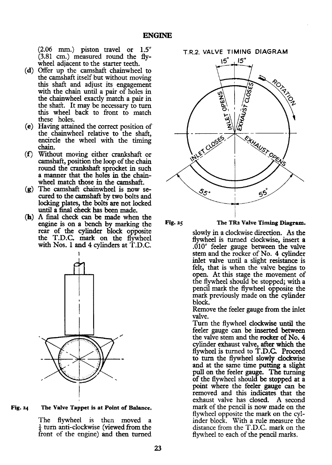
T
R.2.
VALVE
TIMING
DIAGRAM
(3.81
cm.)
measured round the fly-
wheel adjacent to the starter teeth.
(d)
Offer up the camshaft chainwheel to
the camshaft itself but without moving
this shaft and adjust its engagement
with the chain
until
a pair of holes in
the chainwheel exactly match a pair in
the
shart. It may
be
necessary to turn
this wheel back to front to match
these holes.
(e)
Having attained the
correct
position of
the chainwheel relative to the shaft,
encircle the wheel
with
the timing
chain.
(f)
Without moving either crankshaft or
camshaft, position the loop of the chain
round the crankshaft sprocket in such
a manner that the holes in the chain-
wheel match those
in
the camshaft.
(g)
The camshaft chainwheel
is
now se-
cured to the camshaft by two bolts and
locking lates, the bolts
are
not locked
until a
&l
check has
been
made.
I
(h)
A
final
check
can
be
made when the
I
engine is on a bench by marking the
Fig.
25
The
TR2
Valve
Timing
Diagram.
rear of the cylinder block opposite
slowly in a clockwise direction. As the
the T.D.C. mark on the flywheel
flywheel is turned clockwise, insert
a
with
Nos.
1
and
4
cylinders at T.D.C.
.010" feeler gauge between the valve
I
stem and the rocker of No.
4
cylinder
inlet valve
until
a slight resistance is
felt, that is when the valve begins to
open. At this stage the movement of
the flywheel should be stopped;
with
a
pencil mark the flywheel opposite the
mark previously made on the cylinder
block.
Remove the feeler gauge from the inlet
valve.
Turn the flywheel clockwise
until
the
feeler gauge
can
be
inserted
between
the valve stem and the
&er
of
No.
4
cylinder exhaust valve,
after
which the
flywheel is turned to T.D.C. Proceed
to
turn
the flywheel slow17 clockwise
and at the same time pumng a slight
pull on the feeler gauge. The
tuming
of the flywheel should
be
stopped at a
l
point where the feeler gauge
can
be
removed and this indicates that the
exhaust valve has closed.
A
second
Fig.
24
The
Valve
Tappet
is
at
Point
of
Balance.
mark of the pencil is now made on the
flywheel opposite the mark on the cyl-
The flywheel is then moved
a
inder block. With a rule measure the
4
turn
anti-clockwise (viewed from the distance from the T.D.C. mark on the
front
of
the
e~gine) and
theo
turned
fiywhee!
cc
each ef &e
pencil
marks.
23