ENGINE
arises, it is important that the valve guides
are concentric with the seats themselves.
Where a valve guide is badly worn it should
be replaced before the seat is
recut.
While refacing valves, only remove suffi-
cient metal to clean up the face, otherwise
if too much is removed the edge
will
tend
to curl up in service.
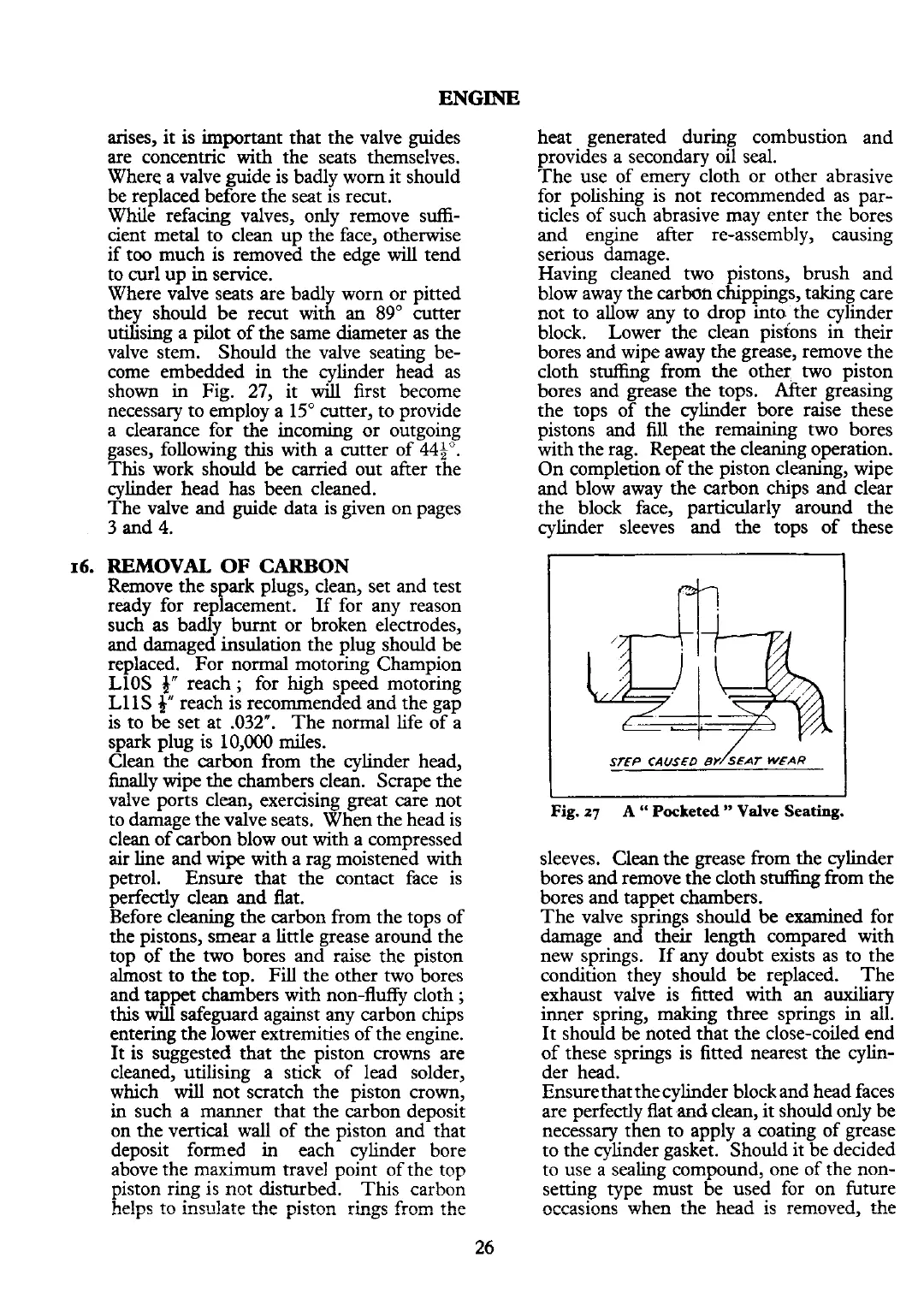
Where valve seats are badly worn or pitted
they should be
recut with an
89"
cutter
utilising a pilot of the same diameter as the
valve stem. Should the valve seating be-
come embedded in the cylinder head as
shown in Fig. 27, it
will
first become
necessary to employ a 15" cutter, to provide
a clearance for the incoming or outgoing
gases, following this with a cutter of
449".
This work should
be
carried out after the
cylinder head has been cleaned.
The valve and guide data is given on pages
3
and
4.
16.
REMOVAL
OF
CARBON
Remove the spark plugs, clean, set and test
ready for replacement. If for any reason
such as badly burnt or broken electrodes,
and damaged insulation the plug should be
replaced. For normal motoring Champion
LlOS
f"
reach
;
for high speed motoring
L1
l
S
f"
reach is recommended and the gap
is to be set at .032". The normal life of a
spark plug is
10,000
miles.
Clean the carbon from the cylinder head,
finally wipe the chambers clean. Scrape the
valve ports
clean,
exercising great care not
to damage the valve seats. When the head is
clean of carbon blow out with a compressed
air
line and wipe with a rag moistened with
petrol. Ensure that the contact face is
perfectly clean and flat.
Before cleaning the carbon from the tops of
the pistons, smear a little grease around the
top of the two bores and raise the piston
almost to the top. Fill the other two bores
and tappet chambers with non-fluffy cloth
;
this
will
safeguard against any carbon chips
entering the lower extremities of the engine.
It is suggested that the piston crowns are
cleaned, utilising a stick of lead solder,
which
will
not scratch the piston crown,
in such a manner that the carbon deposit
on the vertical wall of the piston and that
deposit formed in each cylinder bore
above the maximum travel point of the top
piston ring is not disturbed. This carbon
h~!nr
incrrlgt~ thp njctnn rinuc
frnm
the
r
---------
---
r
-----
---
a-
-----
---
heat generated during combustion and
provides a secondary oil seal.
The use of emery cloth or other abrasive
for polishing is not recommended as par-
ticles of such abrasive may enter the bores
and engine after re-assembly, causing
serious damage.
Having cleaned two pistons, brush and
blow away the carbon chippings, taking care
not to allow any to drop into the cylinder
block. Lower the clean pistons in their
bores and wipe away the grease, remove the
cloth
stuffing from the other two piston
bores and grease the tops. After greasing
the tops of the cylinder bore raise these
pistons and
lill
the remaining two bores
with the rag. Repeat the cleaning operation.
On completion of the piston cleaning, wipe
and blow away the carbon chips and clear
the block face, particularly around the
cylinder sleeves and the tops of
'
these
Fig.
27
A
"
Pocketed
"
Valve
Seating.
sleeves. Clean the grease from the cylinder
bores and remove the cloth stuffing from the
bores and tappet chambers.
The valve springs should be examined for
damage and their length compared with
new springs. If any doubt exists as to the
condition they should
be
replaced. The
exhaust valve is fitted with an auxiliary
inner spring, making three springs in all.
It
should be noted that the close-coiled end
of these springs is fitted nearest the cylin-
der head.
Ensure that thecylinder block and head faces
are
~erfectlv flat
and
clean. it should onlv be
nec&sary then to apply a'coating of .g&ase
to the cylinder gasket. Should it be decided
to
use
a
sealing compound, one of the non-
setting type must be used for on future
nccasinns when the head is removed,
the
 Loading...


