ENGINE
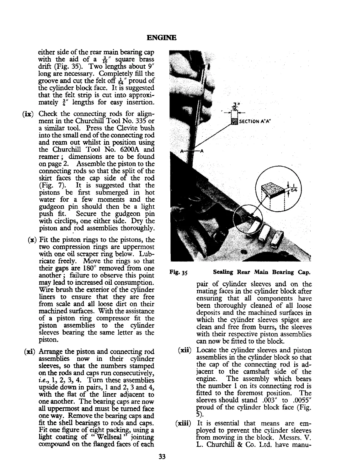
either side of the rear
main
bearing cap
with
the aid of a
A"
square brass
drift (Fig. 35).
Two lengths about
9"
long are necessary. Completely
fill
the
groove and cut the felt off
$4"
proud of
the cylinder block face. It is suggested
that the felt strip is cut into approxi-
mately
a"
lengths for easy insertion.
Check the connecting rods for
align-
ment in the Churchill Tool No. 335 or
a similar tool.
Press the Clevite bush
into the small end of the connecting rod
and ream out whilst in position using
the Churchill Tool No.
6200A and
reamer;
dimensions are to
be
found
on page 2.
Assemble the piston to the
connecting rods so that the split of the
skirt faces the cap side of the rod
(Fig.
7).
It is suggested that the
pistons be first submerged in hot
water for a few moments and the
gudgeon pin should then be a light
push fit.
Secure the gudgeon pin
with circlips, one either side.
Dry
the
piston and rod assemblies thoroughly.
I
Fit the piston rings to the pistons, the
two compression rings are uppermost
with
one oil scraper ring below. Lub-
ricate freelv.
Move the
rings so that
their gaps
ke 180" removed"from one
another
;
failure to observe this point
35
Sealing
Rear
Main
Bearing
Cap.
may lead to increased oil consumption.
pair of cylinder sleeves and on the
Wire brush the exterior of the cylinder
mating faces in the cylinder block after
liners to
ensure that they are free
ensuring that
all
components have
from scale and
all
loose
dirt
on their
been thoroughly cleaned of
all
loose
machined surfaces. With the assistance
deposits and the machined surfaces in
of a piston ring compressor fit the
which the cylinder sleeves spigot are
piston assemblies to the cylinder clean and free from burrs, the sleeves
sleeves bearing the same letter as the with their respective piston assemblies
piston.
can
now be fitted to the block.
e the piston and connecting rod
(4
9
(xii)
Locate the cylinder sleeves and piston
assem lies now in their cyhder assemblies in the cylinder block so that
sleeves, so that the numbers stamped the cap of the connecting rod is
ad-
on the rods and caps
run
consecutively,
jacent to the camshaft side of the
i.e.,
1,
2,
3, 4.
Turn these assemblies engine. The assembly which bears
upside down in pairs, 1 and 2,3 and
4,
the number
1
on its connecting rod is
with
the flat of the liner adjacent to
fitted to the foremost position. The
one another. The bearing caps are now sleeves should stand .003" to .0055"
all
uppermost
and
must
be
turned face proud of the cylinder block face (Fig.
one way. Remove the bearing caps and
5)-
fit the shell bearings to rods and caps.
(xiii)
It is essential that means are em-
Fit one figure
of
eight packing, using a ployed to prevent the cylinder sleeves
light coating of
"
Wellseal
"
jointmg
from moving in the block. Messrs.
V.
compound on
the
Aanged faces ~f each L. Churchill
&
Co.
Ltd. have inanu-
33
 Loading...


