COOLING
solder
run
round the end face to ensure
a water-tight joint (Fig. 10).
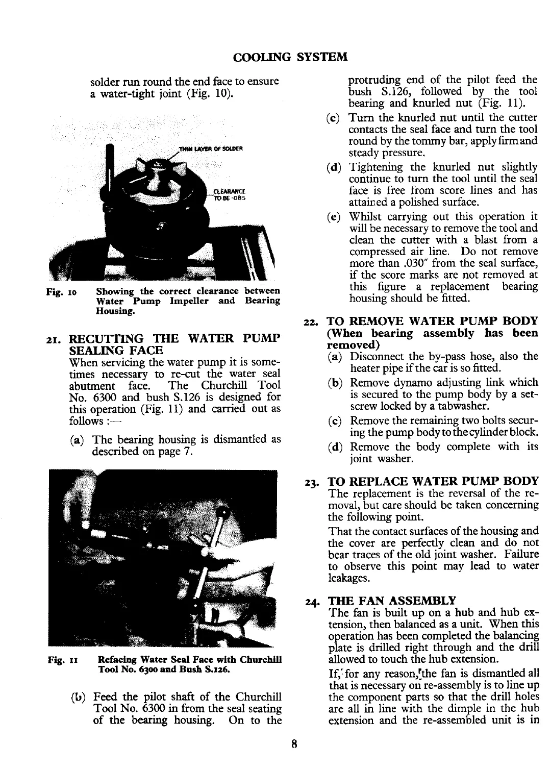
Fig.
21.
10
Showing the correct clearance between
Water Pump Impeller and Bearing
Housing.
RECUTlWG THE WATER PUhW
SEALING FACE
When servicing the water pump it is some-
times
necessary to re-cut the water seal
abutment face. The Churchill Tool
No.
6300
and bush S.126 is designed for
this operation (Fig. 11) and carried out as
follows
:-
(a)
The bearing housing is dismantled as
described on page
7.
Fig.
11
Refacing Water
Seal
Face
with
Churchill
Tool
No.
6300
and Bush
S.126.
Feed the pilot shaft of the Churchill
Tool No.
6300
in from the seal seating
of the bearing housing. On to the
SYSTEM
protruding end of the pilot feed the
bush S.126, followed by the tool
bearing and knurled nut (Fig. 11).
Turn the knurled nut until the cutter
contacts the seal face and turn the tool
round by the
tornmy bar, applyfirmand
steady pressure.
Tightening the knurled nut slightly
continue to turn the tool until the seal
face is free from score lines and has
attained a polished surface.
Whilst carrying out this operation it
will be necessary to remove the tool and
clean the cutter with a blast from a
compressed air line. Do not remove
more than
.030" from the seal surface,
if
the score marks are not removed at
this figure a replacement bearing
housing should be fitted.
TO
REMOVE
WATER PUlMP BODY
(When bearing assembly
has
been
removed)
(a) Disconnect the by-pass hose, also the
heater pipe
if
the car is so fitted.
(b) Remove dynamo adjusting
link
which
is secured to the pump body by a set-
screw locked by a tabwasher.
(c)
Remove the remaining two bolts secur-
ing the pump body tothe cylinder block.
(d) Remove the body complete with its
joint washer.
TO REPLACE WATER PUMP BODY
The replacement is the reversal of the re-
moval, but care should be taken concerning
the following point.
That the contact surfaces of the housing and
the cover are perfectly clean and do not
bear traces of the old joint washer. Failure
to observe this point may lead to water
leakages.
THE
FAN
ASSEMBLY
The fan is built up on a hub and hub ex-
tension, then balanced as a unit. When this
operation has been completed the balancing
plate is drilled right through and the drill
allowed to touch the hub extension.
If,:for any reasonlthe fan is dismantled all
that is necessary on re-assembly is to line up
the component parts so that the drill holes
are all in line with the dimple in the hub
extension and the re-assembled unit is in
 Loading...


