COOLING
SYSTEM
It
will
be
noted that the bolt
is
tra
ped
B
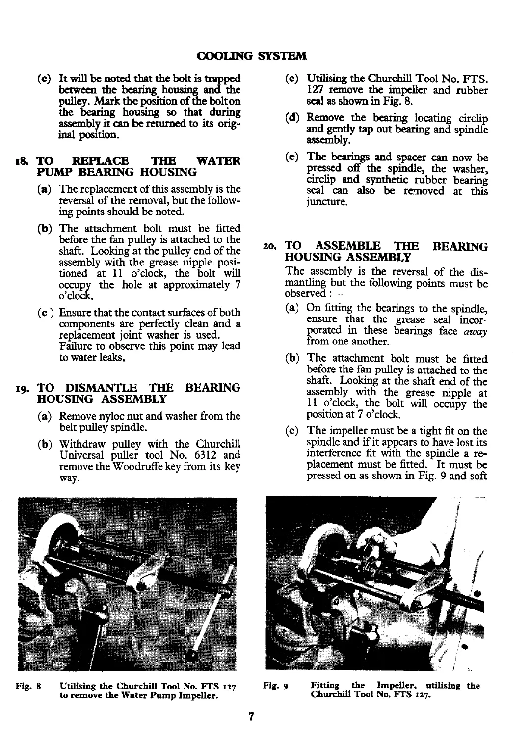
(c)
Utilising
the
Churchill
Tool No.
FTS.
between
the
bearing
housing an the
127
remove the impeller and rubber
pulley.
Mark
the position of the bolt on
seal
as
shown
in
Fig.
8.
the
bearing
housing
so
that
during
assembly
it
can
be
retumed to its orig-
(d)
Remove the
bearing
locating circlip
inal
poution.
and gently
tap
out
bearing
and spindle
assembly.
18.
TO
REPLACE
THE
WATER
(e)
The
bearings
and spacer
can
now
be
PUW BEARING HOUSING
pressed off the spindle, the washer,
circlip and synthetic rubber bearing
The replacement of this assembly is the
reversal of the removal, but the follow-
ing
points should be noted.
The attachment bolt must be fitted
before the fan pulley is attached to the
shaft. Looking at the pulley end of the
assembly with the grease nipple posi-
tioned at
11 o'clock, the bolt will
occupy the hole at approximately
7
o'clock.
Ensure that the contact surfaces of both
components are perfectly clean and a
replacement joint washer is used.
Failure to observe this point may lead
to water leaks.
19.
TO DISMANTLE
THE
BEARING
HOUSING ASSEMBLY
(a)
Remove nyloc nut and washer from the
belt pulley spindle.
(b)
Withdraw pulley with the Churchill
Universal puller tool No. 6312 and
remove the Woodruffe key from its key
way.
seal
-can
als6
be
removed at
thii
juncture.
20.
TO ASSEMBLE
THE
BEARING
HOUSING ASSEMBLY
The assembly is the reversal of the dis-
mantling but the following points must be
observed
:-
(a)
On fitting the bearings to the spindle,
ensure that the grease seal incor-
porated in these bearings face
away
from one another.
(b)
The attachment bolt must be fitted
before the fan pulley is attached to the
shaft.
Looking
at the shaft end of the
assembly with the grease nipple at
11 o'clock, the bolt will occupy the
position at
7
o'clock.
(c)
The impeller must be a tight fit on the
spindle and
if
it appears to have lost its
interference
fit
with the spindle a re-
placement must be fitted. It must be
pressed on as shown in Fig.
9
and soft
Fig.
8
Utilising
the
Churchill
Tool
No.
FTS
127
to
remove
the
Water
Pump
Impeller.
Fig.
9
Fitting
the
Impeller,
utilising
the
Ch~r~hill
Tool
NO.
mS
127.
7