ENGINE
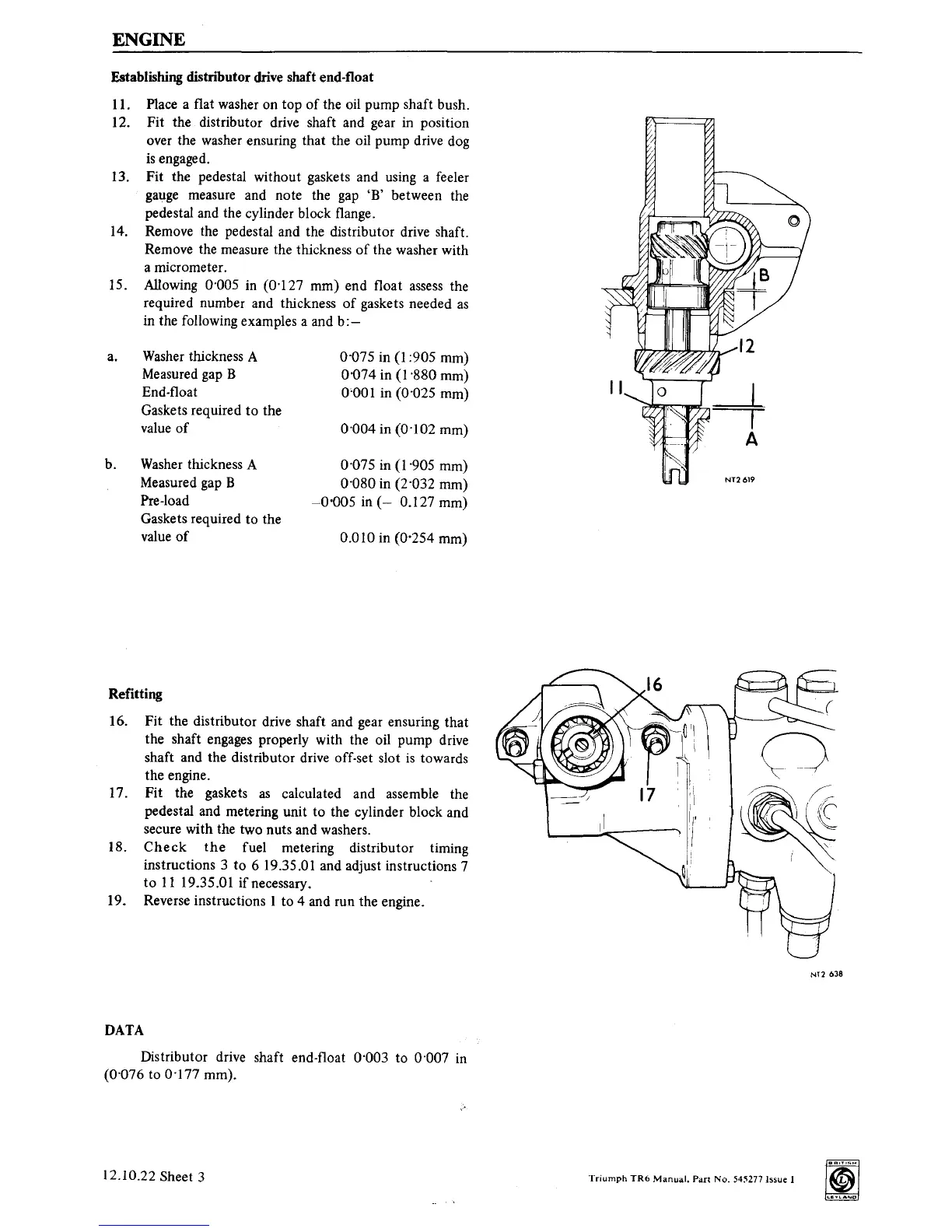
Establishing distributor drive shaft end-float
11. Place a flat washer on top
of
the oil pump shaft bush.
12. Fit the distributor drive shaft and gear
in
position
over the washer ensuring that the oil pump drive dog
is
engaged.
13. Fit the pedestal without gaskets and using a feeler
gauge
measure and note the
gap
'B'
between the
pedestal and the cylinder block flange.
14.
Remove the pedestal and the distributor drive shaft.
Remove the measure the thickness
of
the washer with
a micrometer.
15. Allowing 0·005
in
(0·127 mm) end float assess the
required number and thickness
of
gaskets needed
as
in the following examples a and
b:-
a.
Washer
thickness A
Measured gap B
End-float
Gaskets required
to
the
value
of
b.
Washer
thickness A
Measured gap B
Pre-load
Gaskets required to the
value
of
0·075 in
(I
:905 mm)
0·074 in (1·880 mm)
0'001 in (0·025 mm)
0·004 in (0·102 mm)
0-075 in (1·905 mm)
0·080 in (2·032 mm)
-0'005
in
(-
0.127 mm)
0.010 in (0·254 mm)
Refitting
16. Fit the distributor drive shaft and gear ensuring that
the shaft engages properly with the oil pump drive
shaft and the distributor drive off-set slot
is
towards
the engine.
17. Fit the gaskets
as
calculated and assemble the
pedestal and metering unit to the cylinder block and
secure with the two nuts and washers.
18.
Check
the
fuel metering distributor timing
instructions 3
to
6 19.35.01 and adjust instructions 7
to
11
19.35.0I if necessary.
19. Reverse instructions 1 to 4 and
run the engine.
DATA
Distributor drive shaft end-float 0·003 to 0·007
in
(0·076 to 0·177 mm).
12.10.22 Sheet 3
NT2
638
Triumph
TR6
Manual.
Part
No.
545277 Issue 1
 Loading...


