CONTROLS, INSTRUMENTS ANO INDICATORS
Fig.5
.=
,·=e
•
•
"'"
14
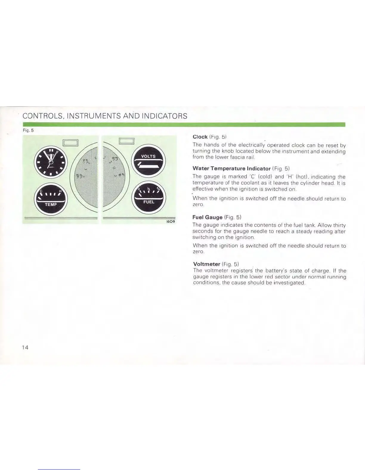
Clock (Fig 5)
The
hands
of
the electrically
operated
clock can be resel by
turning
the knob located
below
the
Instrument
and extendmg
from the lower fascia
rail
Water
Temperature
Indicator (Fig 5)
The
gauge
IS marked 'C' (coldl and
'H'
(hot), Indicating the
temperature
of
the
coolant
as
Illeaves
the cylinder head. It
IS
effective
when
the
Ignition
IS
sWitched
on
When
the
Ignl\lon
IS
switched
off
the needle should return to
zero
Fuel
Gauge
(Fig, 5)
The gauge indicates
the
contents
of
the
fuel tank
Allow
thirty
seconds for the gauge needle to reach a steady readmg after
SWitching
on
the
Ignilion.
When
the
Ignilion
IS
sWl1ched
off
the needle
should
return to
zero
Voltmeter
(Fig, 5)
The
voltmeter
registers the battery's state
01
charge. If the
gauge registers
In
the lower red sector
under
normal
running
conditions. the cause should be Invesllgated,