General information VFL
Application
– Circular volume flow limiters of Type VFL
for the simple balancing of volume flow rates
in air conditioning systems
– Mechanical self-powered volume flow limiter
without external power supply
– Simplified project handling with orders based
on nominal size
– Set the required volume flow rate using a scale
Nominal sizes
– 4", 5", 6", 8", 10"
Special features
– Mechanical self-powered
– Low-friction bellows
– For circular ducts
– Lip seal for tight and secure fit
– Aerodynamically tested and factory set
to a reference volume flow rate
– Sticker showing volume flow rates (in l/s, m³/h
and cfm) that can be set for each limiter
Parts and characteristics
– Ready-to-commission limiter
– Damper blade with low-friction bearings
– Bellows that acts as an oscillation damper
– Leaf spring
– Lip seal
– Multi-level volume flow rate setpoint values
Construction features
– Circular casing
– Lip seal for tight and secure fit
– Acoustically optimized damper blade with
low- friction bearings and special bellows
– Different damper blade construction and
volume flow rate sticker for nominal size 150
Materials and surfaces
– Casing and damper blade made of
high-quality plastic, to UL 94, V1;
to DIN 4102, material classification B2
– Leaf spring made of stainless steel
– Polyurethane bellows
Installation and commissioning
– Any installation orientation
– Set the required volume flow rate using a scale
– Insert the unit into the duct
– Mark the installation location
Standards and guidelines
– Hygiene conforms to VDI 6022
Maintenance
– Maintenance-free as construction
and materials are not subject to wear
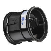
Description
Volume flow limiter
Type VFL
Technical data
Nominal sizes 4 - 10 inches
Volume flow rate range 11 - 450 CFM
Volume flow rate setting range <20 - 100% of the nominal volume flow rate
Volume flow rate accuracy approx. ± 10 % of the nominal volume flow rate
Minimum differential pressure 0.12 in w.g.
Maximum acceptable differential pressure 1.2 in w.g.
Operating temperature 50 – 120 °F
04/2014 US K5 – 2.1 – 3
–
 Loading...