04/2014 US K5 – 2.1 – 9
VFL
Exhaust Register
Application
– The VFL-ER (exhaust register) and VFL-SR
(supply register) are designed for in-wall
installation
– Commonly used to eliminate thermal stack
effect and regulate high rise building pressure
Nominal VFL sizes
– 4", 5", 6", 8" and 10"
Nominal register sizes
– See table below for standard sizes
– Other register heights, widths and depths
available upon request
Special features
– Exhaust or supply orientation
– VFL secured by brackets and sealed to register
– Register can be supplied with aluminum grille
(by TROX) or customized for grille by others
(see p.10 for detaills)
Materials and surfaces
– Adaptor made of 20 ga. galvanized steel
– Natural finish
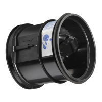
Description
Volume ow limiter
Type VFL (ER & SR)
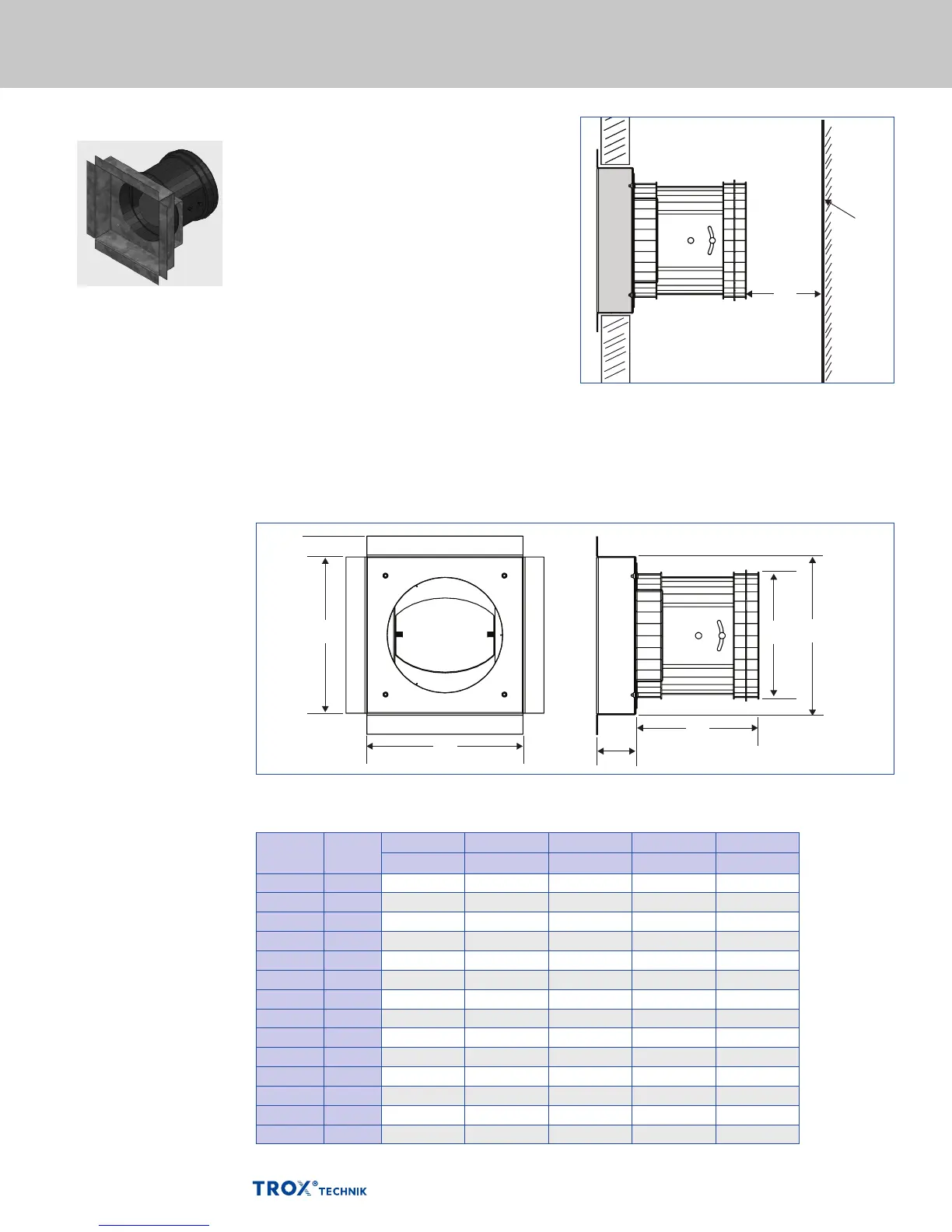
M
OPPOSITE
SHAFT
WALL
*
(Type -ER shown)
Dimensions [in] Register Units Type VFL-ER and VFL-SR
Nominal
duct size
Nominal
VFL size
A B ØD L M
in in in in in
6" x 6" 100 5⅞ 5⅞ 3¾ 4 1
6" x 6" 125 5⅞ 5⅞ 4¾ 4⅝ 1¼
8" x 8" 100 7⅞ 7⅞ 3¾ 4 1
8" x 8" 125 7⅞ 7⅞ 4¾ 4⅝ 1¼
8" x 8" 150 7⅞ 7⅞ 5¾ 5⅞ 1½
10" x 10" 100 9⅞ 9⅞ 3¾ 4 1
10" x 10" 125 9⅞ 9⅞ 4¾ 4⅝ 1¼
10" x 10" 150 9⅞ 9⅞ 5¾ 5⅞ 1½
10" x 10" 200 9⅞ 9⅞ 7¾ 6⅞ 2
12" x 12" 100 11⅞ 11⅞ 3¾ 4 1
12" x 12" 125 11⅞ 11⅞ 4¾ 4⅝ 1¼
12" x 12" 150 11⅞ 11⅞ 5¾ 5⅞ 1½
12" x 12" 200 11⅞ 11⅞ 7¾ 6⅞ 2
12" x 12" 250 11⅞ 11⅞ 9¾ 8⅝ 2½
*Standard sizes shown. Other register dimensions available upon request for any damper and grille size
Dimensional drawing of VFL - ER and - SR exhaust register without fire damper
A
¾″ TYP
B
L
A
ØD
1½˝
*Dimension "M" is the minimum clearance required at the VFL maximum airow rate. Clearance can be reduced for lower ow rates.
Accessories