EasyManua.ls Logo

Troy-Bilt 12068 User Manual

Troy-Bilt 12068
28 pages
To Next Page IconTo Next Page
Page #1 background imageLoading...
Page #1 background image
Question and Answer IconNeed help?

Do you have a question about the Troy-Bilt 12068 and is the answer not in the manual?

Troy-Bilt 12068 Specifications

General IconGeneral
BrandTroy-Bilt
Model12068
CategoryTiller
LanguageEnglish

Summary

Parts Ordering Information

Ordering Replacement Parts

Details required information and procedures for ordering parts from the manufacturer or dealer.

Identification Numbers

Machine Identification Procedures

Instructs users on locating and recording their machine's model and serial numbers for efficient service.

Handlebar Assembly (Figure 1)

Handlebar Components and Hardware

Lists all parts and hardware associated with the tiller's handlebar assembly.

Wheels/Tines/PTO Drive Lever & Yoke Assembly (Figure 2)

Wheel, Tine, and Drive Assembly Parts

Details components for the wheels, tines, PTO drive lever, and yoke assembly.

Wheel Speed Lever, Belt Drive System, Engines, Wheels (Figure 3)

Key Tiller Systems and Components

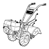
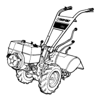
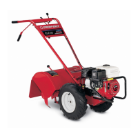
Illustrates and identifies major systems: wheel speed, belt drive, engines, and wheels.

Wheel Speed Lever, Belt Drive System, Engines, Wheels (Figure 3) - Parts

Engine and Mount Parts

Lists parts for the engine mounting and associated hardware.

Depth Regulator & Tine Hood Assemblies (Figure 4)

Power Unit Transmission Assemblies (Figure 5)

Transmission System Components

Shows the overall transmission assembly and its main internal parts.

Power Unit Transmission Assemblies (Figure 5) - Parts

Drive Shaft Assembly Parts

Details components of the main drive shaft assembly.

Power Unit Transmission Assemblies (Figure 5) - Continued Parts

Transmission Housing and Related Parts

Covers the transmission housing and associated seals, bearings, and plugs.

Tiller Attachment Transmission Assemblies (Figure 6)

Tiller Attachment Transmission Components

Illustrates the tiller attachment transmission and its main parts.

Tiller Attachment Transmission Assemblies (Figure 6) - Parts

Bolo Tine Assemblies (Figure 7)

Bolo Tine Assembly Components

Shows the bolo tine assembly, including left and right hand tines.

Bolo Tine Assemblies (Figure 7) - Parts

Forward Interlock System (Figure 8)

Forward Interlock System Components

Illustrates the safety interlock system that prevents forward movement without engagement.

Electric Start System - 7HP & 8HP Tillers (Figure 9)

Electric Start System Components

Shows the battery, starter motor, and wiring for the electric start system.

Dozer/Snow Blade Attachment (Figure 10)

Tine Attachment Cradle (Figure 13)

Row Marker Attachment (Figure 18)

Related product manuals