12 Section 2: Assembly
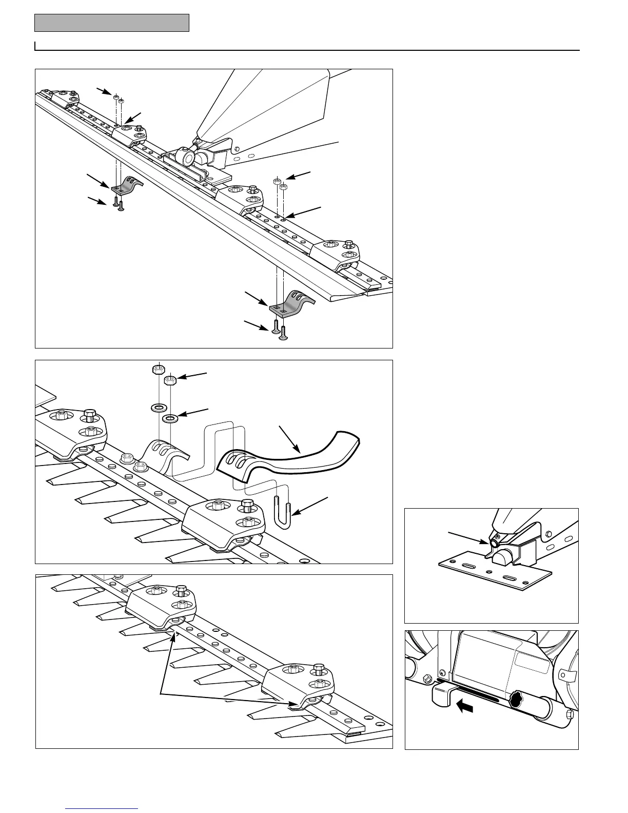
10. As shown in Fig. 2-10A, rotate the
pitman assembly sideways and slide the
shaft on the pitman assembly into the
hole in the eccentric arm (J). Next, rotate
the pitman assembly to its upright posi-
tion and turn the knife head so it is par-
allel with the cutting blade. Finally, align
the small centering pin on the bottom of
the knife head (I) with the middle hole in
the cutter bar (B, Fig. 2-10) and position
the knife head on the cutter bar.
11. Apply Loctite
®
Thread Fastener to the
two 8M x 12M hex head screws (L, Fig. 2-
10A) and place the two 5/16" hardened
washers (K) on the screws. Securely
attach the knife head to the cutter bar with
the two screws (torque to 16-20 ft-lbs if
you have a torque wrench).
12. At the inner set of mounting holes (M,
Fig. 2-11), position the shoe holders (N)
under the cutter bar. Securely attach each
shoe holder with two 5/16–18 x 1" car-
riage bolts (O) and 5/16–18 locknuts (P).
13. Securely attach the shoes (Q, Fig. 2-
12) to the bottom of the holders with a U-
bolt (R), 5/16" flat washers (S) and
5/16"-18 locknuts (T). Adjust the shoes
the same, to level the cutter bar assembly.
14. Oil the area beneath each hold-down
clip (U, Fig. 2-13) on the cutter bar.
15. Move the cutter bar lever (Fig. 2-15)
all the way right to the OFF position.
R
U
S
T
Q
A
 Loading...