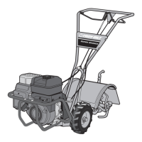
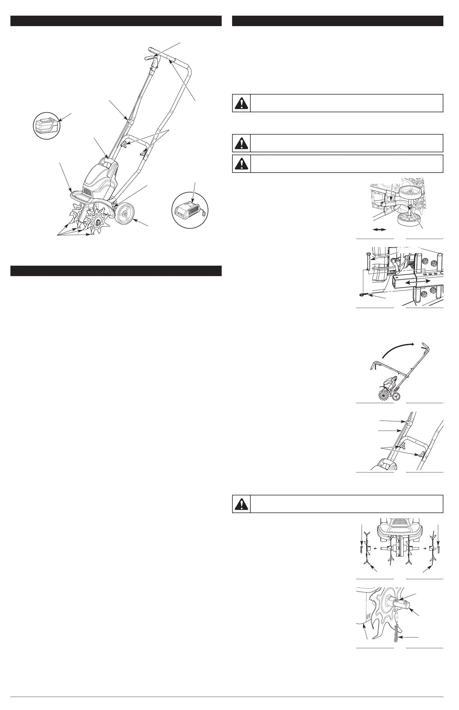
INSTALLING AND ADJUSTING THE WHEEL ASSEMBLY
Installing the Wheel Assembly
1. Remove the cotter pin and the clevis pin from the wheel
assembly.
2. Set the unit on its side (Fig. 1).
3. Insert the wheel assembly into the wheel bracket (Fig. 1).
4. Slide the wheel assembly up or down the wheel bracket.
Raise the wheel assembly for shallower tine penetration
or lower the wheel assembly for deeper tine penetration
(Fig. 1). Align the hole in the wheel assembly with the
desired hole in the wheel bracket.
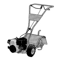
5. Insert the clevis pin through the wheel bracket and
wheel assembly (Fig. 2).
6. Insert the cotter pin into the clevis pin to lock the wheel
assembly in place (Fig. 2).
NOTE: It may be necessary to adjust the position of the
wheel assembly before using the unit.
Adjusting the Wheel Assembly
1. Set the unit on its side (Fig. 1).
2. Remove the cotter pin and the clevis pin from the wheel
bracket and wheel assembly (Fig. 2).
3. Slide the wheel assembly up or down the wheel bracket.
Raise the wheel assembly for shallower tine penetration
or lower the wheel assembly for deeper tine penetration
(Fig. 1). Align the hole in the wheel assembly with the
desired hole in the wheel bracket.
4. Insert the clevis pin through the wheel bracket and wheel assembly (Fig. 2).
5. Insert the cotter pin into the clevis pin to lock the wheel assembly in place (Fig. 2).
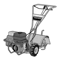
POSITIONING THE HANDLEBARS
1. Loosen the two knobs on the inside of the handlebars
(Fig. 4).
2. With the unit upright, swing the handlebars up into the
operating position (Fig. 3).
NOTE: Take care not to pinch the throttle cable when
positioning the handlebars (Fig. 4).
3. Tighten the knobs to secure the handlebars in place (Fig. 4).
NOTE: Do not over tighten the knobs.
4. Restrain the throttle cable with the cord retainer. Adjust
the throttle cable so it is smooth and tight against the
handlebars.
3
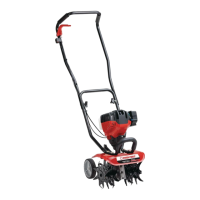
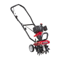
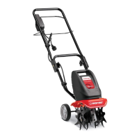
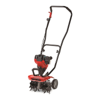
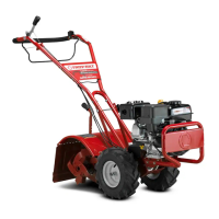
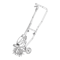
KNOW YOUR UNIT
Handlebar
APPLICATIONS
This unit may be used for the purposes listed below:
• Cultivating sod and light to medium soil
• Cultivating in garden areas, around trees, etc.
Front Handle
Tines
Wheel
Support
Bracket
Wheel
Cord Retainer
Handlebar Knobs
Tine Shield
Throttle Control
Battery
Charger
Battery
SPECIFICATIONS*
* All specifications are based on the latest product information available at the time of printing. We
reserve the right to make changes at any time without notice.
Motor Type. . . . . . . . . . . . . . . . . . . . . . . . . . . . . . . . . . . . . . . . . . . . . . . . . . . Cordless, Battery-powered
Motor Voltage . . . . . . . . . . . . . . . . . . . . . . . . . . . . . . . . . . . . . . . . . . . . . . . . . . . . . . . . . . . . . . . . 20 VDC
Operating RPM . . . . . . . . . . . . . . . . . . . . . . . . . . . . . . . . . . . . . . . . . . . . . . . . . . . . . . . . up to 7,000 rpm
Cultivating Path Width (Maximum) . . . . . . . . . . . . . . . . . . . . . . . . . . . . . . . . . . . . . . 9 inches (22.86 cm)
Cultivating Depth (Maximum) . . . . . . . . . . . . . . . . . . . . . . . . . . . . . . . . . . . . . . . . . . 5 inches (12.70 cm)
Approximate Weight (with battery) . . . . . . . . . . . . . . . . . . . . . . . . . . . . . . . . . . . . . . . 27.24 lb. (12.35 kg)
Battery . . . . . . . . . . . . . . . . . . . . . . . . . . . . . . . . . . . . . . . . . . . . . . . . . . . . . . . . . . . . . . . . . . 20V Lithium
Charge Time. . . . . . . . . . . . . . . . . . . . . . . . . . . . . . . . . . . . . . . . . . . . . . . . . . . . . . . . . . . . . . . . . 2 Hours
Battery Weight. . . . . . . . . . . . . . . . . . . . . . . . . . . . . . . . . . . . . . . . . . . . . . . . . . . . . . . 3.24 Lbs. (1.47 kg)
Optimum Charging Temperature . . . . . . . . . . . . . . . . . . . . . . . . . . . . . . . . . . . 32° to 86° F (0° to 30° C)
Battery Charger Input . . . . . . . . . . . . . . . . . . . . . . . . . . . . . . . . . . . . . . . . . . . . . . . 120 V 60 Hz AC only
Battery Charger Weight . . . . . . . . . . . . . . . . . . . . . . . . . . . . . . . . . . . . . . . . . . . . . . . . 1.2 Lbs. (0.54 kg)
ACCESSORIES
Model #
TB20V . . . . . . . . . .
TBCHGR . . . . . . . .
Description
20V Lithium-ion Battery
20V Lithium-ion Battery Charger
Part #
49MLI55L966. . . . . . . . .
49MALBCL966. . . . . . . .
NO ASSEMBLY TOOLS REQUIRED
ASSEMBLY INSTRUCTIONS
Fig. 3
Fig. 4
Throttle
Cable
Handlebar
Knobs
Cord
Retainer
Fig. 1
Lower
Wheel Bracket
Raise
Wheel Assembly
Fig. 2
Clevis Pin
Cotter Pin
This unit requires assembly.
UNPACKING
• Carefully remove the product and any accessories from the box.
• Inspect the product carefully to make sure no breakage or damage occurred during shipping.
• Do not discard the packing material until you have carefully inspected and satisfactorily operated
the product.
• If any parts are damaged or missing, please call 1-800-828-5500 (U.S.) or 1-800-668-1238 (Canada)
for assistance.
WARNING:
To avoid injury from the tines, wear heavy gloves and a long sleeve shirt when
adjusting the wheel assembly.
WARNING: To prevent serious personal injury, do not install the battery until the unit is fully
assembled.
WARNING: To prevent serious personal injury, the wheel assembly must be installed when
operating the unit.
ASSEMBLING THE UNIT WITH ONLY TWO TINE ASSEMBLIES (OPTIONAL)
If desired, the unit can be assembled with only two tine
assemblies to produce a narrower cultivating path.
1. Lay the unit back on a flat level surface with the handles
touching the ground so that the unit is in a horizontal
position.
2. Remove the click pin found at the end of each tine shaft
(Fig. 5).
3. Carefully remove the two outer tine assemblies from the
tine shafts (Fig. 5).
4. Insert a large cotter pin into the hole in the tine shaft that
is closest to the gearbox (Fig. 6). Perform this step for
both sides.
NOTE: Store the click pins and extra tine assemblies in a
safe place. Refer to Cleaning and Storage.
WARNING: Cultivator tines are sharp. Always wear leather gloves to protect your hands
when handling tines.
Fig. 5
Outer Tine Assemblies
Click Pin
Fig. 6
Tine Shaft
Click Pin
Large
Cotter Pin
Hole
Gearbox
 Loading...