100mm
TP Screw (3x20mm)
6mm
100mm
6mm
6mm
Main wing joiner
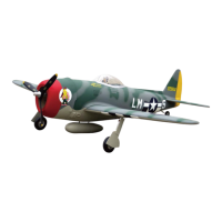
1
Securely glue together. If coming off during flights, you 'll
lose control of your airplane which leads to accidents!
Cut away the shaded portion for assembling
the gear house very well.
Rib template (2mm ply)
2
Wood dowel (6x30mm)
1
6mm
6mm
8
TP Screw (3x20mm)
Epoxy the main wing together tightly.
Assemble the retract to the right place.
Drill holes to appropriate position in the wings
and epoxy wood dowels in them.
And trim holes for draging servo lines out as illustration below.
Drill holes to relevant position in the fuselage.
Epoxy the wheel house to the wings carefully.
According to the rib template drill holes to the wing
root and epoxy the wooden dowel in them.
16
18
17
20
21
4
19
Steel wire
Copper joiner
Aluminum tube
Clevis
Add a rubber ring around the
clevis for insuring safety!
nut 6mm
25mm
40mm
10mm
40mm
25mm
10mm
Fuel tank (550cc)
1
Collar (3mm)
3
1
1
1
Tail landing gear
Tail gear supporter
Tail wheel (45mm)
2
2
2
Steel wire (0.5x3000mm)
Copper joiner
Aluminum tube(3x6mm)
1
Tail gear supporter
Clevis
2
1
1
Ply (3mm)
Nut (6mm)
1
Nose arm(3mm)
1
Tail landing gear(3mm)
TP Screw(3x20mm)
Washer (3x6mm)
4
4
Ply (6mm)
1
Collar
Tail landing gear
Collar
Collar
The sketch map when assemble the tail landing
gear to the wheel steeling mount.
1
Clevis
Washer(3x15mm)
Washer
Lock Nut (3mm )
Screw (3x30mm)
Screw (2x10mm)
Rod (2x300mm)
Plastic tube (2x1000mm)
3mm
3mm
Fiberglass pushrod
(8x650mm)
1
2x200mm Rod
2x300mm Rod
Clevis
2x200mm Rod
8x650mm Rod
250mm
250mm
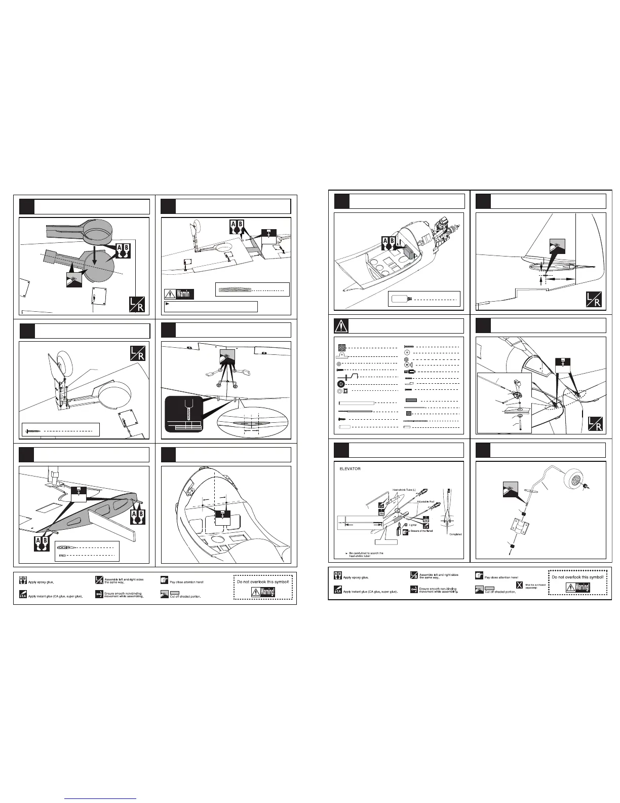
Assemble the linkage rods for elevator and rudder.
110mm
20mm
Rod (2X300mm)
Heat-shrink Tube(12x30mm)
3
4
1
Plastic tube (2x200mm)
5
4
4
2
Clevis
1
Retainer
Screw (3x35mm)
2
Washer(3x15mm)
Lock Nut (3mm )
Washer(3x15mm)
1
Screw (3x80mm)
2
Screw (2x10mm)
8
TP Screw (2.3x8mm)
Ply (15x15x3mm)
8
Drill holes to appropriate position in the tail fuselage.
Install the control horn to relevant position in the elevator
and connect the linkage.
2
Plastic tube(3x50mm)
Epoxy the fuel tank to the fuselage
According to the standard position draw lines.
Install the tail landing gear.
Open a hole at the tail bottom as illustration.
Epoxy the plies to the right position and leave the
holes all open
43
45
46
47
9
48
44
Accessory list for the coming installation steps.
 Loading...