Do you have a question about the Troy Built Models P-47D Thunderbolt and is the answer not in the manual?
Adjust control surface travel to diagram values, then readjust as needed for flight.
Assemble retracts, ensuring pressure inlet sealing and correct connections before flight.
Reposition receiver/battery to achieve specified CG; never fly unbalanced.
Not a toy. Seek experienced advice, fly in open areas, and read all manuals.
Requires a minimum 6-channel radio, 12 AA-size batteries, and glow engine fuel.
Requires a Model Airplane Engine (4-cycle .120), muffler, fuel filter, and glow engine fuel.
Includes propeller, spinner, engine starter, and glow plug for engine operation.
Gather essential tools like knives, screwdrivers, pliers, cutters, and scissors.
Read the manual thoroughly and check all parts for defects or missing items.
Understand the symbols used and pay attention to warnings for safe assembly.
| Paint Required | Yes |
|---|---|
| Glue Required | Yes |
| Decals Included | Yes |
| Radio | 4 channel |
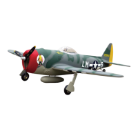
| Material | Balsa |
| Skill Level | Intermediate |