000907SP10
INSTALLING AND REMOVING BRAKE PADS
BREAK-IN PERIOD
A) Changing Brake Pads
· Remove wheel from bike.
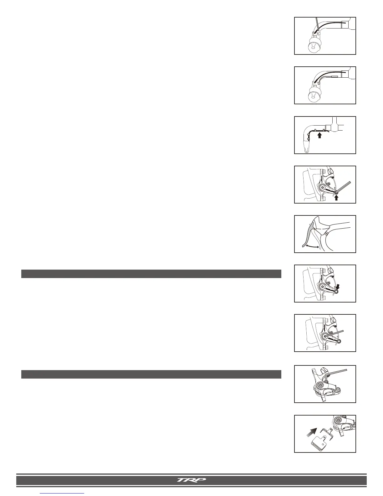
· Pull the cotter pin from the brake pad retaining bolt – be careful not to lose this piece – and loosen the bolt
with a 3mm allen key. Set the bolt and cotter pin aside. [Fig. F-1]
· Slowly pull the bolt out of its sleeve while placing your palm over the rotor end of the brake pads to catch them
when they are released. Be careful to save the spring assembly for later use.
· Remove the pads from the bottom end of the caliper.
· Install new pads and spring assembly into the calipers. [Fig. F-2]
· Reinsert brake pad retainer bolt into the caliper and re-attach the cotter pin. Tighten the brake pad assembly
bolt. Be sure that the small tabs on the ends of the pads are properly aligned and seated in the notch on the
top of the caliper.
· Repeat for other caliper and adjust cable or pad alignment if necessary.
A) Break In Period
Disc brakes have a 30-40 cycle break-in period to achieve optimal pad seating and performance. Exercise
caution for the first 30-40 cycles each time you replace the brake pads.
SAFETY CHECK
Before Every Ride:
· Spin Wheel to be sure rotor is undamaged and aligned
· Check brake pad thickness, if pads are less than 0.8mm replace
· Check bolt tension, re-torque if necessary
· Check cable and housing for fraying, excessive friction or damage.
· Ensure that all cables are secured to frame and/or fork and can not contact tires!
C) Cable Installation
· Compression-less housing, (linear strand) is recommended for SPYRE Mechanical Disc Brakes to yield the best
performance. Sealed ferrules or other sealing systems are not recommended as they may create excess friction
and affect the brake lever return performance. Route housing to minimize tight bends and acute angles.
· Install a small section of spiral wound housing that inserts into the brake lever body and runs inside or outside
the first bend in the bar as shown. (Not all brake lever bodies need a ferrule installed - check with your brake
lever manufacturer’s technical documents to determine if a ferrule is
needed) The ends should be filed flat and
the liner should be open to eliminate friction. Install a double-ended ferrule. [Fig. C-1 & C-2]
· Spiral wound housing can be cut to accomodate bar widths and preferences, such as hiding the double
ended ferule under bar wrap. Allow spiral wound housing to extend at least 25mm, (1 inch) beyond the handle-
bar bend. [Fig. C-3]
· Install the compression-less housing on the remainder of the frame or fork. Cut accurately to minimize tight
bends and acute angles to optimize the brake lever feel.
D) Connecting the Brake
· Turn barrel adjuster so that it is fully threaded in. Install ferrule on end of compression-less housing to fit in barrel
adjuster.
· Run cable through and attach to SPYRE actuation arm. The arm should be slightly preloaded to create cable
tension. [Fig. D-1]
Spyre & Spyre Mtn: Tighten bolt with a 5mm Allen wrench and tighten to 4-6Nm (35 - 53 in-lb.)
Spyre SLC - Tighten 3mm cable screw to 2.5-3.0 Nm (22 - 27in-lb.)
· To align the caliper, reattach the wheel, pull the brake lever firmly to self-align the caliper on the rotor and
tighten the caliper mounting bolts to 6 – 8 Nm (53 – 71 in lbs).
· Release the lever and check that the pads are aligned equally and that the wheel spins freely. The barrel
adjuster may be used to fine tune brake lever feel.
· Pull brake lever 10 times to strech cable and seat housing. Push back on the actuation arm - if it is not returning
fully, this indicates there is too much friction that will need to be corrected for best performance.
[Fig. D-2 & D-3]
· New cable will stretch after initial installation. Repeat cable tightening process to maintain proper perfor-
mance.
E) Fine-tuning
There are two ways to fine-tune the caliper to improve lever feel: the barrel adjuster and the pad adjuster.
· Thread the barrel adjuster out to take up cable slack or compensate for pad wear.
· Using a 3mm allen wrench, turn the pad adjustement screw clockwise (located in the outboard piston) to
compensate for pad wear or imrpove lever feel. You may need to re-align the caliper. [Fig. E-1]
For questions about setup, usage or general inquiries, please contact TRP by e-mail at
info@trpbrakes.com or by phone toll free in US, 877-807-4162 or outside US 1-801-648-7079.
C-1. Check if ferrule is needed
on your brand brake lever
C-2. Install spiral wound housing
for handlebar bend
C-3. Housing min. length
D-1. Preload arm and tighten
D-2. Squeeze lever 10 times
D-3. Check arm return
E-1. Pad adjustment screw
F-2. Replace pads and holder
F-1. Unscrew pad retainer bolt
Spiral Wound,
(continous)Housing
PUSH
 Loading...