12
TRUE RESIDENTIAL
™
NOTE: DIMENSIONS MAY VARY BY ±
1
/
8
”
ANTI-TIP KIT INSTALLATION
ANTI-TIP BRACKET KIT:
• One (1) anti-tip bracket (Figure 1.1)
• Four (4) masonry 3/16" screws
• Eight (8) wood #12 – 2" screws
• Twelve (12) 1/4" washers
FOR ALL FULL SIZE RESIDENTIAL MODELS, THE ANTI-
TIP BRACKET ENGAGES WITH THE REAR LEVELING
LEGS TO SECURE THE UNIT. FOLLOW THESE STEPS
TO SECURE THE BRACKET BEFORE MOVING THE
UNIT INTO FINAL OPERATING POSITION.
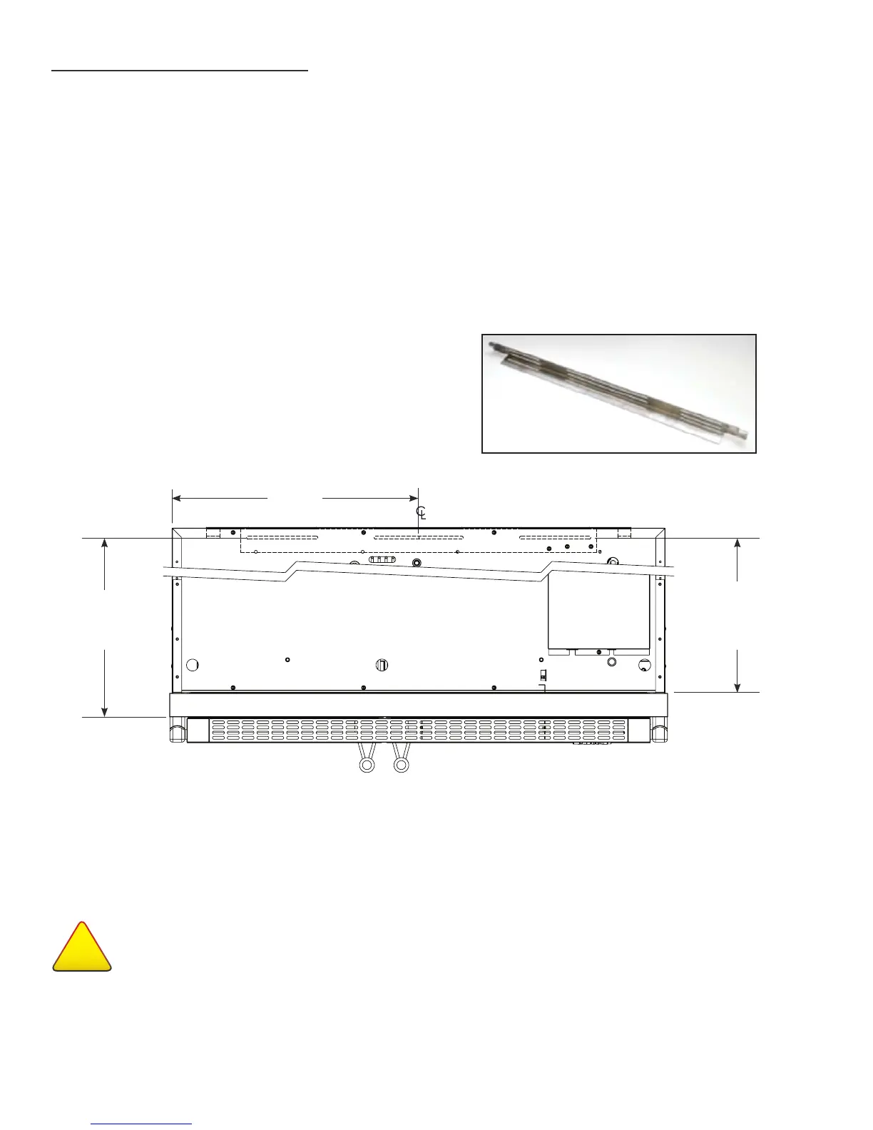
1. Determine final location of the unit. For a FLUSH
install, measure back 24-31/32" (Dimension A)
from the surrounding cabinetry. For a PROUD
install, measure back 22-31/32" (Dimension B)
from the surrounding cabinetry. For either type of
install, place the anti-tip bracket centered in the
rough opening.
2. Using the bracket as a guide, drill pilot holes into
the floor and wall. It is recommended to secure the
bracket to as many floor joists and wall studs as
possible.
3. Using the provided screws and washers, secure the
bracket to the wall/floor. Adjust the rear rollers to
just above their lowest position and move the unit to
its final position. Raise the rear rollers a minimum
of 1/8" to engage the bracket.
FIGURE 1.1 - ANTI-TIP BRACKET
NOTES:
• BECAUSE OF THE WEIGHT OF THIS UNIT (720 LBS), IT IS RECOMMENDED TO CONSULT A
FLOORING EXPERT PRIOR TO INSTALLATION. THE FLOORING BENEATH THE UNIT SHOULD BE
RATED TO SUPPORT AT LEAST 150 POUNDS PER SQUARE FOOT.
• EIGHT (8) ¼-20 X 1" LAG BOLTS SECURING THE UNIT TO THE SKID DURING SHIPPING MAY
ALSO BE USED ON THE INSTALLATION OF THE ANTI-TIP BRACKET.
WARNING
!
TIP OVER HAZARD
A child or adult could tip the refrigerator resulting in property damage or bodily harm. Follow these instructions
to properly install the anti-tip device. If the unit is moved, verify the device is properly engaged before normal
usage of unit commences.
Dimensions may vary by ± 1/8”
DIMENSION A
Flush Install
24
31/32
"
20
25/32
"
DIMENSION B
Proud Install
22
31/32
"