The data label is located on
the side of the unit, beside
the indoor air outlets.
Fig. 7
Intended use
This device was designed for installation inside mobile homes
and caravans. Any other applications are only possible after
consultation with Truma.
Regulations
Any alteration to the unit, or the use of spare parts and func-
tionally-important accessories which are not original Truma
components, or failure to respect the Installation and Operat-
ing Instructions, will lead to the cancellation of the guarantee
and to the ex clusion of claims for liability.
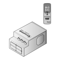
Air conditioner kit
The air conditioner kit contains
1 Pre-assembled air conditioner
16 Screws 19 x 4 mm (pointed)
1 Outer wall grill cover
11 Screws 19 x 4 mm (flat)
10 Plastic spacers
1 Tensioning belt
2 Securing brackets
1 Wall switch with 3 m cable
1 Return air filter
1 Installation template
1 Set literature
Choice of location
Always install the unit in such a way that it is easily accessible for
service work at all times and can be easily removed and installed.
Note
In order to achieve uniform cooling / heating of the vehi-
cle, the air-conditioning unit must be installed centrally in a
stowage box or similar mounting in such a way that the air
distribution ducts can be laid vertically in covered areas (e.g.
in clothes cupboards).
The air-conditioning unit is mounted on the floor. The indoor
air which is to be cooled / heated is drawn in directly by the
unit via an additional air grille in the stowage box wall (acces-
sory, part no. 40040-29200) or via other apertures with a total
surface area of at least 300 cm².
Installation instructions
Caution
The indoor air will be purified and dried while the unit is in op-
eration. Accordingly, if the unit is installed in external stowage
containers (e.g. double floors) suitable steps must be taken to
ensure that the air which is to be cooled / heated is extracted
from the interior of the vehicle. The intake of indoor air from
the outside can severely impair the effect of the air-condition-
ing system.
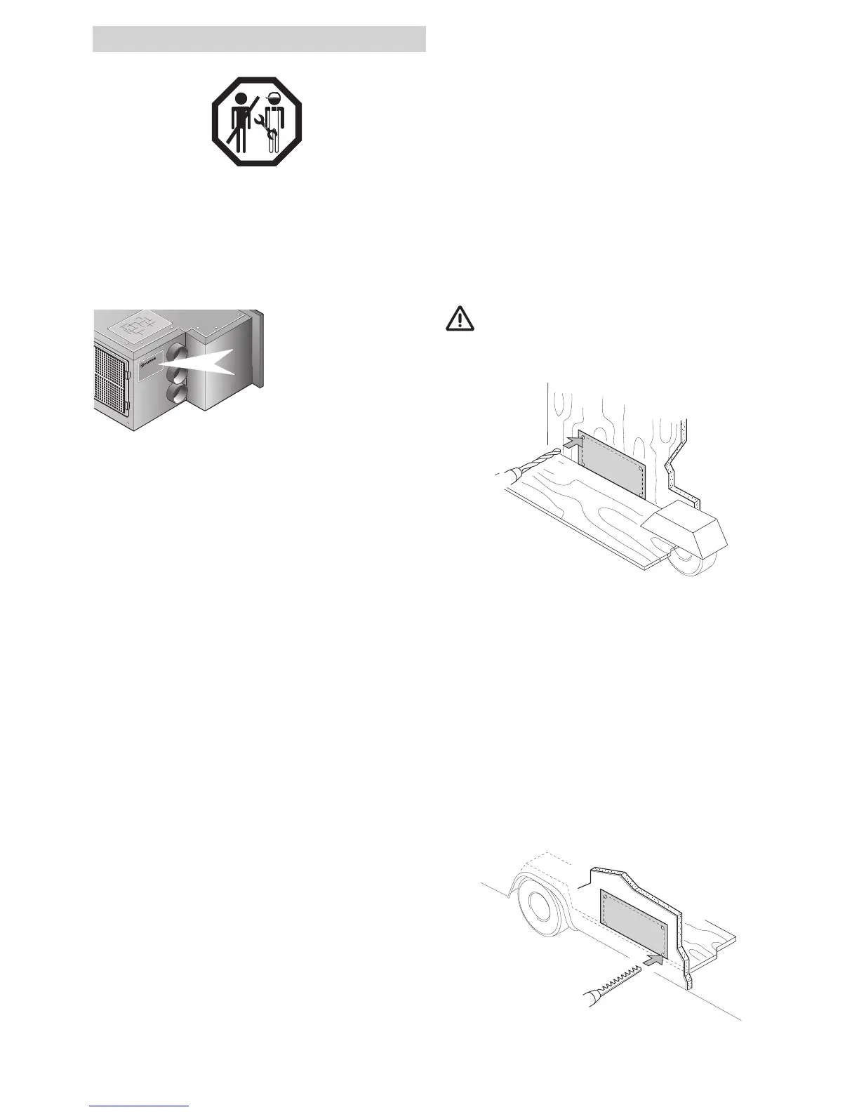
Template
Take the template provided and seperate it on the dotted
line (C) to two templates.
Inside the caravan
1. Temporarily tape the wall aperture template inside the
stowage compartment in which the unit is intended to install
and check the spatial conditions for the wall aperture.
The apertures in the vehicle must be freely accessible
and must not be covered by any frame elements or
similar objects located behind them. Structural sections
within the walls of the caravan should be avoided for
safety reasons.
A
A
B
B
C
Fig. 8
2. After checking the spatial conditions, align the aperture
template as shown and fix in position with adhesive tape.
Important Note
Ensure that the bottom line (C) is on the floor!
3. Drill 2 holes (A) with 10 mm dia. through the wall. Ensure
that the drill is kept square to the wall.
Outside the caravan
The 2 holes drilled through the wall will allow the template to
be positioned correctly on the outside wall.
1. Align the position of the template with the 2 holes drilled
and tape to the outside wall. Ensure that the template is
square to the caravan body.
A
A
B
B
C
Fig. 9
2. Drill 2 holes (B) and check that the bottom line (C) is level
with the caravan floor.