5
1 1
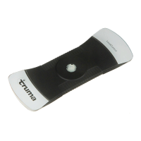
Figure 2
Steel gas cylinders
If the Truma LevelControl is not held by the magnets on
the gas cylinder, perform the steps described under
“ Aluminium gas cylinders”.
Fit the Truma LevelControl with the coupling pad(1) centrally
on the cylinder base.
90°
Figure 3
Aluminium gas cylinders
The separately available clamping sheet is required for secur-
ing (see “Accessories”)
Danger of cut injuries! Wear protective gloves (con-
forming to EN 388 ref. no. 3221) when securing the
clamping sheet.
Do not pull the Truma LevelControl along the gas cylin-
der base, as this can damage the coupling pad (1).
When securing the clamping sheet, make sure that the Truma
LevelControl is not pushed along the cylinder base.
Adjust the clamping sheet to option A or B, depending on
the gas cylinder size. Rotate the swivel plate (6) through 90°
until it engages. For option B, also rotate the swivel plate (7)
through 180° until it engages.
Option A
6
Figure 4
Option B
7
6
Figure 5