9
Electrical
connection 12 V
Electric cables, switching
units and control units for
heaters must be arranged in
the vehicle in such a way that
their satisfactory operation
cannot be adversely affected
under normal operating con-
ditions. All cables leading to
the outside must be splash
proof at the leadthrough
opening.
Prior to working on electric
components the appliance
must be disconnected from
the power supply. Switching
off at the control panel is not
sufficient!
When carrying out electric
welding work on the body
the appliance connection
must be disconnected from
the vehicle electrical system.
If the connections are
transposed there is a
risk of cable burning. This al-
so rules out any guarantee or
liability claims.
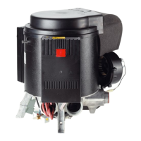
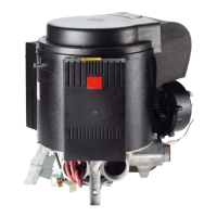
Fig. N: To guarantee opti-
mum power supply, the heat-
ing system must be connect-
ed to the fused on-board net-
work (central electronics unit
10 A) with a 2 x 2.5 mm
2
cable (for lengths over 6 m
with 2 x 4 mm
2
cable). If rele-
vant, voltage drops in the
supply cable must be taken
into account. Connect the
negative lead to the central
earth. If connected directly to
the battery, the positive and
negative leads must be
fused. Use fully-insulated 6.3
mm push-on receptacles (57)
for the connection.
Do not connect any other
consumers to the supply line!
When using power packs,
please observe that the
appliance is only to be oper-
ated with safety extra-low
voltage in accordance with
EN 60742!
The Truma battery
charger NT 12/3-18
(Art. no. 39901-01) is recom-
mended if several 12 V de-
vices are being connected.
This charger (18 A charging
current) is also suitable for
charging lead storage batter-
ies. Other chargers are only
to be used with a car battery
12 V as buffer. Power packs
and power supply equipment
must have a stabilized 12 V
output (ripple content less
than 1 V).
For saving the battery
we recommend using
solar collectors. Please ask
for information from your
dealer.
Electrical connection
of the safety/drain
valve
Fig. G: Connect the valve
with the red continuous cur-
rent cable (+) to the fused ve-
hicle power supply (1 A).
Connect the 2-pin cable with
double connector (58) to the
control unit. The brown cable
(59) is provided for the re-
mote control of the safety/
drain valve (refer to operating
instructions – accessories).
Electrical
connection 230 V
(special version)
The electrical connec-
tion is only to be car-
ried out by an expert (in Ger-
many, acc. to VDE 0100, Sec-
tion 721). The information giv-
en here is not intended as in-
structions for you to carry
out. It is for assisting the ex-
pert assigned to carry out the
job, acting as auxiliary infor-
mation when connecting the
appliance!
Connection to the mains sup-
ply is effected by means of
cables 3 x 1.5 mm
2
(e.g. hose
line H05VV-F) to a distributor
box (not included in the
scope of supply).
Always make sure to connect
carefully, observing the cor-
rect colours!
For maintenance and repair
work a disconnecting device
must be provided on the ve-
hicle for all-pole disconnec-
tion from the power supply,
with at least 3 mm contact
clearance.
Mount splitting box near to
the appliance – on the vehicle
floor or on the wall (length of
cable: 90 cm).
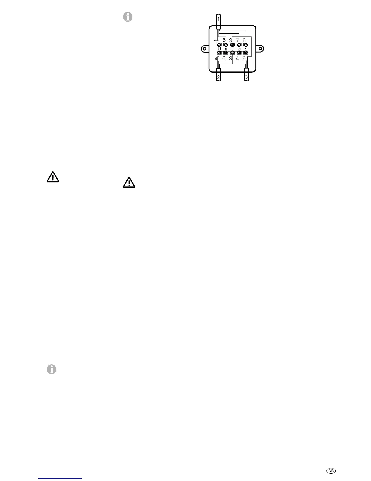
Connect operating unit cable,
feed lead 230 V, and heat
sleeve cable as shown in the
illustration.
1 = Control panel cable
2 = Supply 3 x 1.5 mm
2
3 = Heating collar cable
4 = brown
5 = green
6 = blue
7 = yellow
8 = white
9 = yellow/green
All cables must be secured
with cable clips.
Function check
After installation, the gas
feed line must be tested for
tightness by the pressure-
drop method. A test certifi-
cate (in Germany, for exam-
ple, in accordance with
DVGW Worksheet G 607 for
motor vehicles or G 608 for
boats) is to be issued.
Then check all functions of
the appliance, as specified in
the operating instructions, in
particular the water content
draining function.
There shall be no claims
under guarantee for dam-
age caused by frost!
The operating instructions
and completed guarantee
card are to be given to the
owner of the vehicle.
Warning information
The installer or vehicle owner
must apply the yellow sticker
with the warning information,
which is enclosed with the
appliance, to a place in the
vehicle where it is clearly vis-
ible to all users (e.g. on the
wardrobe door)! Ask Truma
to send you stickers, if neces-
sary.
 Loading...