20
Notes on installation in boats
Installation in boats must accord with the technical and ad-
ministrative provisions of the individual country of use (e.g.
EN ISO 10239 for boats). National specifications and regula-
tions (in Germany, for example, DVGW Worksheet G 608)
must be respected.
The “Guidelines for the Construction, Installation, Testing and
Operation of Liquid Gas Systems for Household Purposes
on Inland Waterways” (BGR 146) must be complied with in
Germany. According to these guidelines the liquid gas system
must be installed by an engineer who has been approved by
the inland waterways employer’s liability associations and
tested by experts belonging to these employer’s liability insur-
ance associations.
In other countries always observe the respectively valid
regulations.
It is not possible to install heaters with floor cowl.
For further notes on installation, refer to the assembly instruc-
tions for the Trumatic E boat heater.
Choice of location
Always install the appliance and its exhaust duct in such a
way that it is always easily accessible for service work and can
be removed and installed easily.
For evenly distributed heating, the installation of the appliance
should be as much in the centre of the vehicle as possible (or
under the vehicle), and in such a way that the air distribution
ducts can be routed with approximately the same length.
The cowl must be placed in such a way that exhaust gas can-
not find its way into the vehicle interior.
The wall cowl is to be fitted in such a way that no tank nozzles
or tank ventilation apertures are located within 500 mm (R) of
it. In addition, no air discharge apertures for the living area or
window openings may be located with 300 mm (R) of it.
300 mm
300 mm
R
If installing the cowl directly underneath a window
that will be opened, installation of an electric window
switch (part no. 34000-85800) is mandatory. The gas unit
must automatically switch itself off using the Truma automatic
shut-off facility if the window is opened (Accessories, part no.
39050-00800).
Exhaust duct
With the Trumatic E 2400 only use the Truma exhaust duct
AA 24 (part no. 39420-00) for the installation with wall cowl,
and for boats use the Truma stainless steel exhaust duct
AEM 24 (part no. 39430-00) and the combustion air supply
duct ZR 24 (part no. 39440-00) as the appliance has only been
tested and approved with these ducts.
A new O-ring must always be installed after dismantling
the exhaust duct!
Permissible duct lengths
1. Interior installation with wall cowl
(refer to installation variant 1, page 2):
– Duct lengths of up to max. 70 cm can be routed as
ascending duct in any way required, or descending by
max. 30 cm.
– Duct lengths from 70 cm to max. 150 cm must be
routed as ascending duct with an ascending angle of
min. 45°.
2. Under-floor assembly with wall cowl
(refer to installation variant 4, page 2):
– Cowl double duct length max. 70 cm, routed as
ascending duct in any way required or descending by up
to 30 cm.
Interior installation using the wall
cowl kit
Refer to installation variant, Fig 1 (page 2).
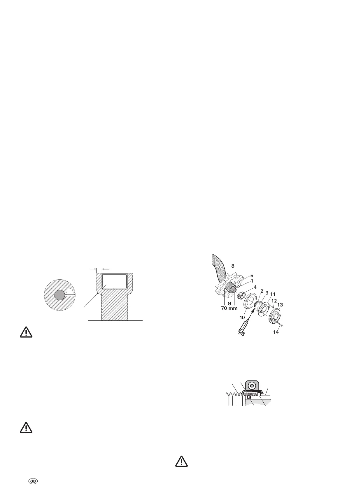
Assembly of wall cowl
Assemble wall cowl on a surface which is as flat as possible
and which is exposed to wind from all directions. Drill an
opening (8) measuring 70 mm in diameter (pack wood into
hollow spaces in the area of the cowl opening). Use the pro-
vided rubber seal (10) for sealing. In the event of structured
surfaces, coat with plastic body sealant – do not use silicone.
In the event of a greater wall thickness, first connect the
exhaust double duct to the cowl from the outside.
Slide rubber seal (10) and clamp (4) onto the cowl inner
part (11).
Press end of ex-haust duct (1) together so that winding
touches winding, slide over the O-ring (2a) on the connection
fitting (2) up to the collar (3 – cowl bend pointing upward) and
tighten clamp (4) in such a way that the knurled edge of the
clamp encloses the collar.
1
4
2
3
2a
Coat serrated connection fitting (9) with plastic body seal-
ant – do not use silicone! – and slide over combustion air sup-
ply duct (5).
Fasten cowl inner part (11) with 3 screws (12 – observe instal-
lation position! The Truma lettering must be at the bottom).
Mount cowl outer part (13) and screw on with 2 screws (14).
Always install a new O-ring following any disassembly!