24
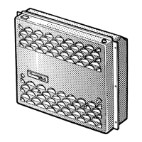
Installing the control panel with slide switch
For existing installation sections.
Remove the cover screen from the installation section.
Plug the control panel cable (10) into the control panel (8),
feed it to the rear through the installation section, and lay it to
the control panel.
Push the control panel (8) in until the front face is flush with
the surface.
If there is no installation section present, the control
panel can be fitted with the flush-fitting installation frame
provided.
If flush mounting is not possible, Truma will supply an on-
surface frame (part no. 39050-11600) as an accessory on
request.
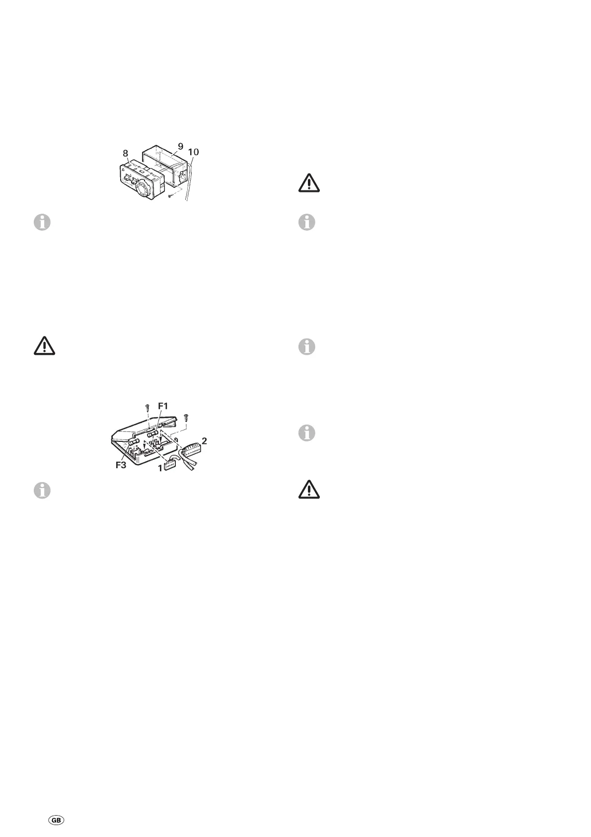
Fitting the electronic control unit
Unscrew the cover of the control unit.
The plug on the electronic control unit should only be
withdrawn or plugged in if the supply voltage had been
disconnected beforehand. Pull the plug out straight!
Insert the plug on the control panel cable (1) as shown in the
diagram onto the red terminal strip of the control unit.
If a timer switch or a fine sensor is fitted, its plug is to be
inserted on the black terminal strip. If several accessory
components are being used at the same time, connection is
effected via the multiple socket (Accessories).
Secure the lower part with two screws at an easily accessible
location, protected against moisture (must not be heated to
above 65 °C).
Screw the cover of the control unit into place.
If the appliance is assembled on the outside of the vehicle,
the electronic control unit must be installed inside the vehicle,
where it is protected against moisture and damage.
Drill an opening of 25 mm diameter in the floor or wall, dis-
connect connector (2) of 20-pin cable form the control unit
and pass through the opening. Seal with cable grommet. Re-
insert connector.
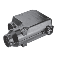
In special cases, the electronic control unit can be assembled
on the outside of the vehicle, in a protective box, for the elec-
tronics on the outside (Accessories, part no. 39950-00).
Electrical connection 12 V / 24 V
Electric cables, switching units and control units for heaters
must be arranged in the vehicle in such a way that their satis-
factory operation cannot be adversely affected under normal
operating conditions. All cables leading to the outside must be
splash proof at the leadthrough opening.
Prior to working on electric components the appliance
must be disconnected from the power supply. Switch-
ing off at the control panel is not sufficient!
When carrying out electric welding work on the body the
appliance connection must be disconnected from the vehicle
electrical system.
If the connections are transposed there is a risk of cable
burning. This also rules out any guarantee or liability
claims!
The red cable is positive, the blue cable is negative!
Connect the appliance to the fused vehicle electrical system
(central electrical system 5 – 10 A) using the 2 x 1.5 mm
2
cable, for lengths over 6 m use 2 x 2.5 mm
2
cable. Negative
cable to central ground. For direct connection to the battery
the positive and negative cable must be fused. Connections in
Faston terminals, fully insulated (motor vehicle flat connector
system, 6.3 mm).
Do not connect any other consumers to the supply line!
When power packs or power supply units are being
used, note that the output voltage is between 11 V
and 15 V and the alternating current ripple is < 1.2 Vpp. The
Truma battery charger NT 12/ 3-18 (part no. 39901-01) is
recommended for connecting multiple 12 V devices. This
charger (with a charging current of 18 A) is suitable for
charging lead-acid or lead-gel batteries. Other chargers may
be used only with a 12 V battery as a buffer.
For saving the battery we recommend using solar collec-
tors. Please ask for information from your dealer.
Gas connection
The operating pressure of the unit (30 mbar, see type
plate) must be the same as the gas supply‘s operating
pressure.
The gas supply line (8 mm dia.) must be attached to gas-con-
nection muff with olive screw fitting. Carefully counterhold
with another spanner when tightening!
The gas connecti on fitting on the appliance is not to be short-
ened or bent.
Prior to connecting the appliance make sure that the gas lines
are free from dirt, chips and such!
Choose to route the pipes in a way that will facilitate removing
the unit for service tasks.
Keep the number of parting connections in the gas supply
line in rooms frequented by people to a technically feasible
minimum.
The gas system must accord with the technical and adminis-
trative provisions of the individual country of use (in Europe,
for example, EN 1949 for motor vehicles or EN ISO 10239 for
boats). National regulations and rulings (in Germany, for exam-
ple, the DVGW worksheet G 607 for motor vehicles or G 608
for boats) must be respected.
 Loading...