3
DESCRIPTION
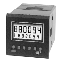
This add or subtract counter has a two line LCD readout with the count on the Main
Display and the preset value on the Subsidiary Display. Two internal replaceable lithium
batteries power the module, maintain the data and operate the output relay. Battery life of
8 years can be expected.
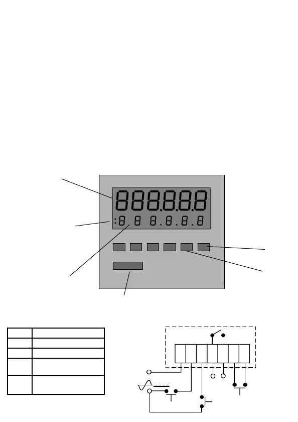
The output is via a relay which can be programmed either as normally open (NO) or
normally closed (NC). Reset and presetting can be carried out from the front panel
although the keys can be remotely disabled from the rear of the unit. The count and
reset inputs are opto-isolated and will accept an input voltage up to 250v AC or DC.
Connection is by a single 7-way plug-in screw terminal block.
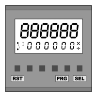
FRONT PANEL
The key below each digit sets the preset value on the Subsidiary Display. The red reset
key resets the unit to zero when count is adding or to the preset value when subtracting.
This function can be automatic (see page 3). The keys for decades 1, 2 and Reset are
also used for programming (see page 3).
The relay symbol illuminates whenever the output relay is active and the decimal point
can be set up to 3 decimal places.