12
15. Plug in and install cover plate.
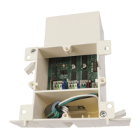
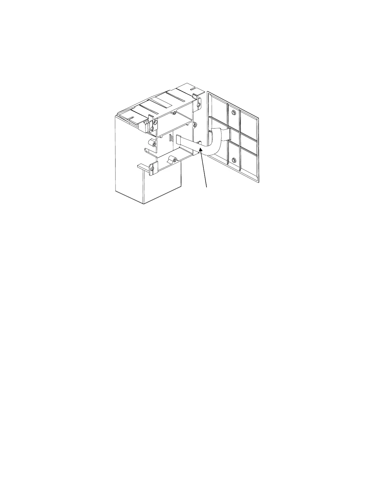
Plug in the ribbon cable from the wall plate onto control board (See No. J1 on wire diagram)
Note: orientation of plug is critical to correct wall switch and LED functions. The dull side of the
ribbon cable faces toward the board (the shiny side with paper tag faces toward side of wall box),
If functions are reversed (blind buttons controlling window etc..) the ribbon plug needs to be
reversed.
16. Establishing Operating Memory.
Upon pressing the open button the unit will cycle through a full “open and close” range
(this may take up to 3 minutes depending on application), during this time the “Red” LED
will be lit and the unit will establish the operating memory which is then stored and
protected from loss.
Dull side faces in
inin
in
(Toward board)
(Toward board)(Toward board)
(Toward board)