Do you have a question about the TSi Power ATS-500 Series and is the answer not in the manual?
The ATS series of automatic transfer switches is designed for applications where two or more autonomous power sources are available.
This document contains safety alert pictorial Symbols and Words that point out areas and procedures that require special attention.
Accepts inputs from asynchronous sources and can be used with most supply voltages, including out-of-phase.
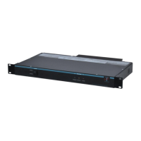
The ATS-500 enclosure dimensions are 11.25" wide x 3" high x 10" deep for Hardwire units.
The ATS-500 enclosure is constructed of 18 gauge steel, finished with a liquid black polyester powder coating.
Access points for DB-9 Connector, circuit breakers, termination compartments and plugs/receptacles.
Top view with cover removed showing main wiring and major components.
Diagram showing the flow of power from primary and backup sources to the ATS output.
Details on the main control circuit boards used in the ATS Series models.
Description of PZ00120-5 and PZ00127-5 Main Control Circuit Boards.
Explains the function of the Green, Yellow, and Red LEDs on the display board.
Details the DB-9 connector for remote monitoring of ATS status and alarms.
Describes the two-pole circuit breakers connecting Primary and Backup AC to the ATS unit.
Guidance on choosing a suitable location and preparing the installation site for the ATS unit.
Lists the standard hand tools and wire strippers needed for installation.
Instructions for carefully unpacking, inspecting units for damage, and handling claims.
Steps to change the voltage transfer points on the ATS unit by adjusting jumpers.
Procedures for attaching mounting brackets and positioning the unit at the desired location.
Notes on torque terminations, safety codes, and wire gauge for hardwire connections.
Step-by-step guide to test the ATS functionality after installation.
Connecting load equipment after successful ATS functional testing.
Information on using the DB-9 connector for remote monitoring of ATS status and alarms.
Guidelines for field repair, focusing on circuit board replacement and ordering parts.
Procedure for returning faulty circuit boards to TSi Power for repair or exchange.
TSi Power recommends keeping 3-5% spare boards for large installations.
Detailed technical specifications for MC80023 ATS-500 Series Hardwire models.
Technical specifications for MC80024 ATS-500 Series Plug and Receptacle models.
Technical specifications for MC80025 ATS-500 Series IEC 230V models.
Specifications for MC80026 ATS-500 Series 208/220/240V Plug and Receptacle models.
Specifications for MC80027 ATS-500 Series 208/220/240V Hardwire models.
Specifications for MC80028 ATS-500 Series 230V Hardwire models.
Specifications for MC80029 ATS-500 Series Hardwire Input, IEC Output models.
Specifications for MC80030 ATS-500 Series 230V Hardwire models.
Details on different product configurations, model numbers, and their specifications.
Contact details for TSi Power Corporation, including address, phone, fax, and email.
| Input Voltage | 100-240 VAC |
|---|---|
| Input Frequency | 50/60 Hz |
| Output Voltage | 100-240 VAC |
| Output Frequency | 50/60 Hz |
| Management Type | Web-based, SNMP |
| Power Supply | Internal |
| Certifications | CE, FCC, RoHS |
| Operating Temperature | 0°C to 40°C |
| Weight | 3.5kg |