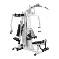
IG. 45 Attach a Nylon Pulley 4 1/2 Rd. (#35) to the
ront Upright (#3) and secure it using one Hex Head Cap
crew 3/8-16 X 3 3/4 (#75), two Flat Washers SAE 3/8 (#90),
ne Nylon Insert Jam Lock Nut 3/8-16 (#86) and one Cable
etainer Bracket (#111). Then continue to route the Lat
able (#14) over the pulley as shown. Refer to Fig. 1 on page
7 and Fig. B on page 18 for further detailed illustration of this
able routing.
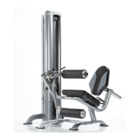
FIG. 46 Assemble the Double Pulley Plates 1/8 X 2 X
(#21) using two Nylon Pulleys 4 1/2 Rd. (#35), two Hex Head
Cap Screw 3/8-16 X 1 3/4 (#79), four Flat Washers SAE 3/8
(#90) and two Nylon Insert Jam Lock Nuts 3/8-16 (#86). Refer
to Fig. 1 on page 17 for further detailed illustration of this
cable routing. Next, route the Lat Cable (#14) through the
Double Pulley Plates 1/8 X 2 X 9 (#21), as shown above.
Note: The four holes on the Double Pulley Plates 1/8 X 2 X
(#21) are used to adjust the cable tension once the cable
routing has been completed.
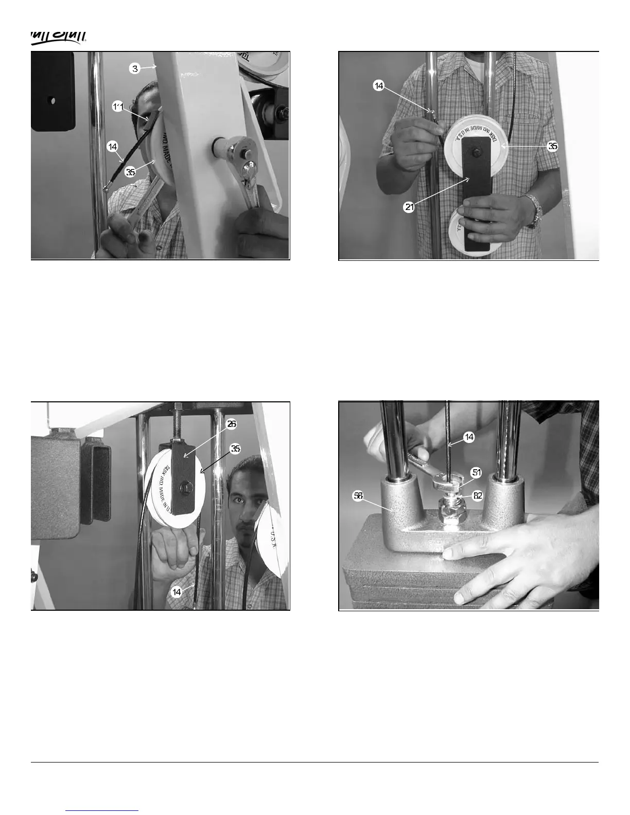
IG. 47 Insert a Nylon Pulley 4 1/2 Rd. (#35) into the
djustable Pulley Bracket (#26) and secure it using one Hex
ead Cap Screw 3/8-16 X 1 3/4 (#79), two Flat Washers SAE
/8 (#90) and one Nylon Insert Jam Lock Nut 3/8-16 (#86).
oute the Lat Cable (#14) through the Adjustable Pulley
racket (#26), as shown above.
FIG. 48 Attach the Lat Cable (#14) to the Top Plate /Selecto
Bar (#58) and secure it using one Split Bolt 1/2-13 X 1 (#51) a
one Split Washer 1/2 (#82). Refer to Fig. E on page 18 for
further detailed illustration of this assembly. Note: Be sure this
hardware assembly is securely fastened.
MSL-IV Muscle IV Home Gym
13
 Loading...