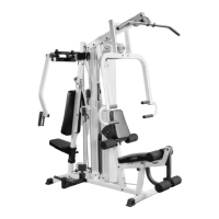
IG. 17 Insert the two Guide Rods (#20) into the
eceptacle of the Base Frame (#2), as shown above. Next,
nsert two Rubber Donuts 1 X 2 1/2 (#41) onto each each
uide Rod (#20). Note: Lubricate the Guide Rods (#20) with
ilicone or teflon lubricant at this time.
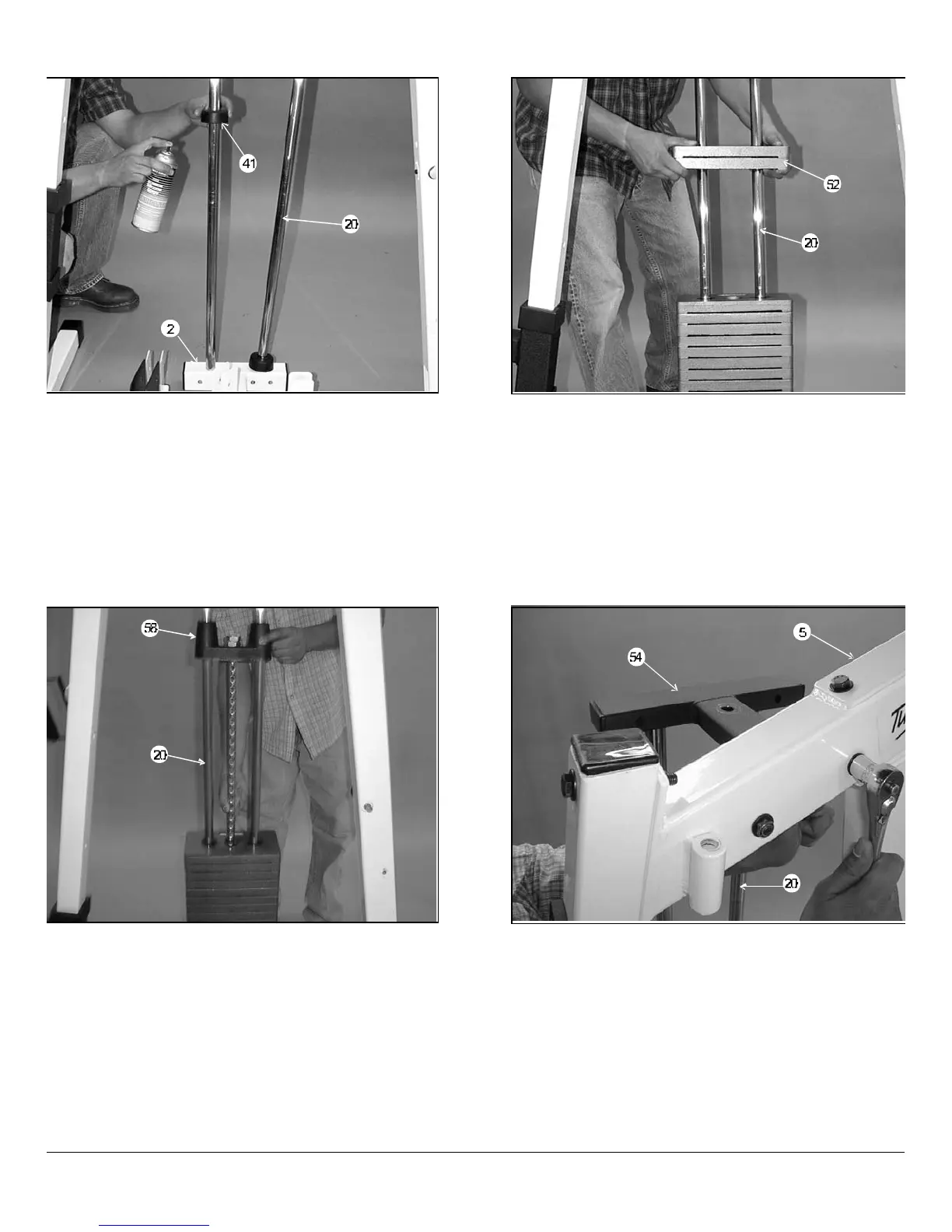
FIG. 18 Carefully begin sliding the 10 Lb. Weight Plates
(#52) over the Guide Rods (#20),one or two at a time as our
skill permits. Make sure that the 10 Lb. Weight Plates (#52)
are installed onto the Guide Rods (#20) in numerical order,
beginning with the number 200 at the bottom,190 next, and s
on.
IG. 19 Now slide the Top Plate/Selector Bar (#58) over
he Guide Rods (#20) allowing it to come to rest on the
ompleted weight stack.
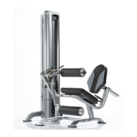
FIG. 20 Maneuver each of the Guide Rods (#20) into the
holes on the bottom side of the Guide Rod Retainer (#54).
Next, mount the Guide Rod Retainer (#54) along with the two
captive Guide Rods (#20) to the side of the Top Pulley
Assembly (#5). Secure this assembly using two Hex Head
Cap Screws 3/8-16 X 3 (#94), four Flat Washers SAE 3/8
(#90) and two Nylon Insert Jam Lock Nuts 3/8-16 (#86).
Owners’ Manual: Assembly Instruction
SL-IV Muscle IV Home Gym
6