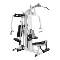
IG. 21 Locate the Adjustable Pulley Bracket (#26) and
hread a Hex Nut 1/2-13 (#88) and a Flat Washer SAE 1/2
#89) onto it. Use the illustration above for further clarification
f this bolt and nut assembly. Next, insert the Adjustable
ulley Bracket (#26) into the Guide Rod Retainer (#54) and
ecure it using one Nylon Insert Jam Lock Nut 1/2-13 (#88)
nd one Flat Washer SAE 1/2 (#89). Note: Loosely secure the
ut to allow adjustment for cable tension later in the assembly
rocess.
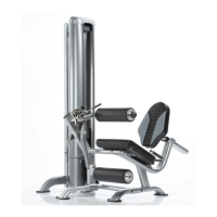
FIG. 22 Insert the Lat Bar Holder (#22) into the tube-end o
the Top Pulley Assembly (#5), as shown above. Secure this
assembly using one Hex Head Cap Screw 3/8-16 X 2 1/2
(#78), two Flat Washers SAE 3/8 (#90) and one Nylon Insert
Jam Lock Nut 3/8-16 (#86).
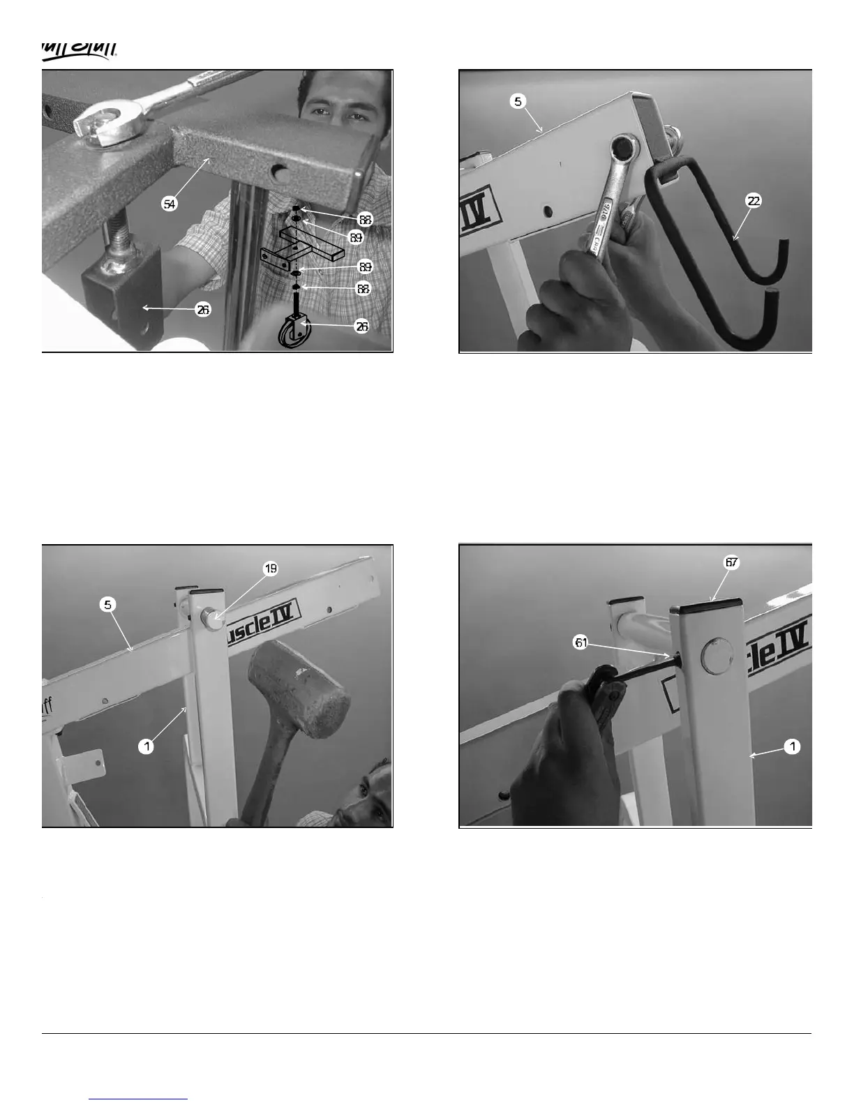
IG. 23 Now position the Press Arm (#1) to the Top Pulley
ssembly (#5), as shown above. Next, press the Pivot Axle 1
11 3/4 (#19) through the holes in the Press Arm (#1) using
rubber mallet hammer until it is flush with both sides. Note:It
s recommened that the Pivot Axle 1 X 11 3/4 (#19) be
reased prior to this assembly.
FIG. 24 At the top of each end of the Press Arm (#1) is a
set screw fixture. Secure the Press Arm (#1) using two Set
Screws 3/8-16 X 1/2 (#61). Use the Hex Key 3/16 (#50) tool fo
securing the Set Screws 3/8-16 X 1/2 (#61). Next, insert two
Plastic Insert Caps 1 X 2 (#67) into the tube-ends of the Press
Arm (#1).
MSL-IV Muscle IV Home Gym
7
 Loading...