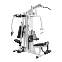
IG. 25 Locate the Range Of Motion Device (#48), the
arge Cable Retainer (#107) and two Nylon Pulleys 4 1/2 Rd.
#35). Assemble as shown using one Hex Head Cap Screw
/8-16 X 3 (#94), three Nylon Spacers 3/8 X 3/8 (#72), two Flat
ashers SAE 3/8 (#90) and one Nylon Insert Jam Lock Nut
/81-6 (#86). Refer to Fig. C on page 18 for further clarification
f this assembly.
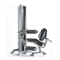
FIG. 26
Next, locate the Black Caster 2 X 1 (#34) and two
Nylon Spacers (#72). Assemble to the Range Of Motion
Device (#48) using one Hex Head Cap Screw 3/8-16 X 2 3/
(#77), two Flat Washers SAE 3/8 (#90) and one Nylon Inser
Jam Lock Nut 3/8-16 (#86). Refer to Fig. Con page 18 fo
further clarification of this assembly.
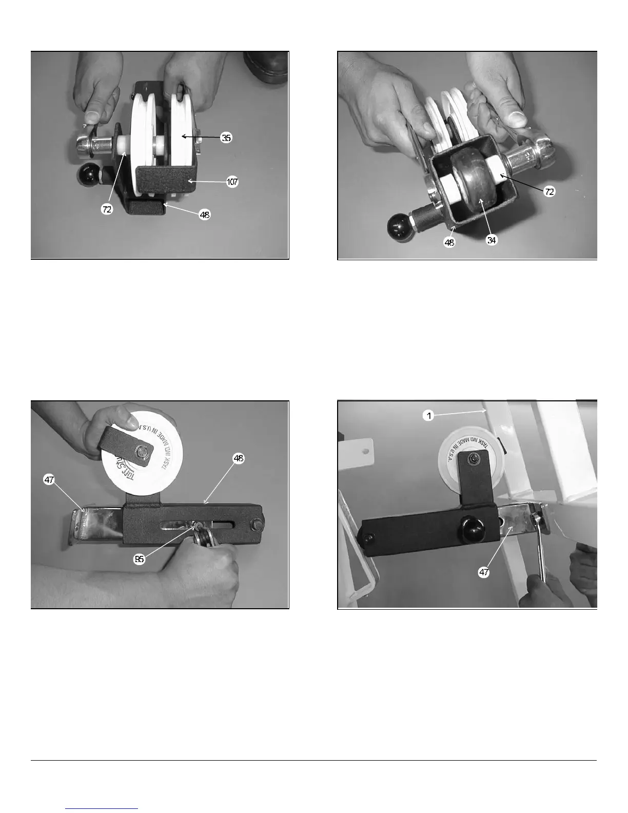
IG. 27 Locate the Range Of Motion Tube (#47) and one
houlder Bolt 3/8 X 3/8 (#95). Insert the Range Of Motion
ube (#47) into the Range Of Motion Device (#48), as shown
bove. Secure this assembly using the Hex Key 3/16 (#50).
FIG. 28 Attach the Range Of Motion Tube (#47) onto th
Press Bar (#1) and secure it using two Hex Head Cap Screws
3/8-16 X 3 1/4 (#76), four Flat Washers SAE 3/8 (#90) and tw
Nylon Insert Jam Lock Nuts 3/8-16 (#87).
Owners’ Manual: Assembly Instruction
SL-IV Muscle IV Home Gym
8
 Loading...