19
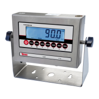
FIGURE 3: INNER TERMINAL BLOCK CONNECTION DIAGRAM
Table 4. Wiring Color Code
Signal Name Color Code Description
+Exe/ +EX RED Positive excitation voltage to load cell
+IN / +SIG GREEN Positive output signal from load cell
HD / SHLD YELLOW/THICK BLACK Shield Wire
-IN / -SIG WHITE Negative output signal from load cell
-EXC / -EX BLACK Negative excitation voltage to load cell
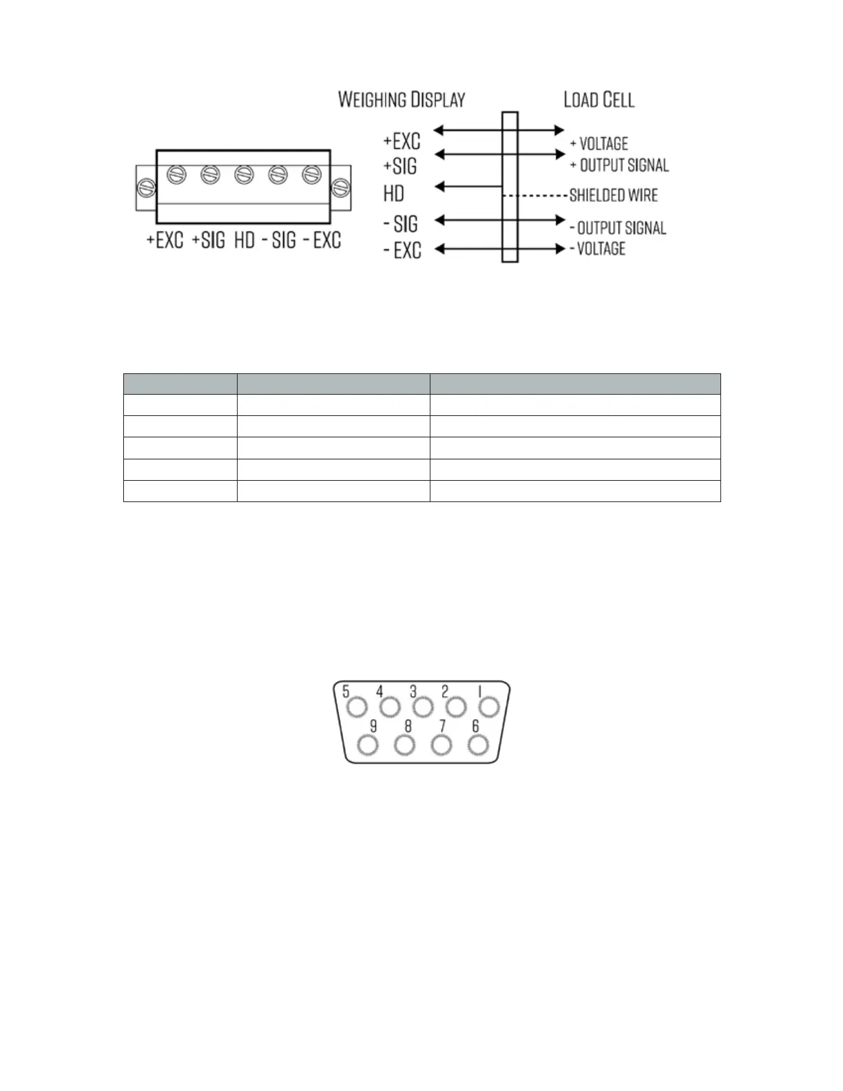
DB9 Connection (9 pin Serial Connector)
The DB9 9 pin serial connector is used for different purposes depending on the
indicator model
● Figure 4 shows the pin assignment on the DB9 9 pin connector
FIGURE 4: DB9 SERIAL CONNECTOR PINOUT
There are 3 Output formats to choose from
1. RS232 Serial Output Format (Standard)
2. 4-20 mA Analog Output (Optional)
3. Relay Output (Optional)
 Loading...