EasyManua.ls Logo

Turbosmart e-Boost 2 User Manual

Default Icon
3 pages
To Next Page IconTo Next Page
Page #1 background imageLoading...
Page #1 background image
e-Boost 2 QUICK START GUIDE
Wiring
- The e-Boost2 must be connected to a 12 volt negative earth electrical system.
- All electrical connections must be soldered.
- Refer to the following table and diagram for detail on wiring the e-Boost2.
Wire
Connect to
RED
+ 12 Volts switched through ignition – connect via 5 Amp fuse supplied
BLACK
Chassis, earth or ground
GREY
Solenoid wire 1 – connect using wire supplied – polarity not important
BROWN
Solenoid wire 2 - connect using wire supplied – polarity not important
YELLOW
RPM signal from ECU or negative terminal of an ignition coil
WHITE
Auxiliary output – switched to ground – see diagram below
GREEN
External set point switching
ORANGE
External set point switching
Solenoid hook up method (Basic setup)
Internal wastegate setup: Port 1 (Vent), Port 2 (Internal wastegate actuator), Port 3 (Pressure only)
External Wastegate setup: Port 1 (Vent), Port 2 (Bottom port of wastegate), Port 3 (Pressure only)
For advanced hook up methods, please read the complete E-Boost 2 manual
1) Enter Setup menu by pressing MODE and SETUP/UP at the same time.
Question and Answer IconNeed help?

Do you have a question about the Turbosmart e-Boost 2 and is the answer not in the manual?

Turbosmart e-Boost 2 Specifications

General IconGeneral
BrandTurbosmart
Modele-Boost 2
CategoryController
LanguageEnglish

Summary

Wiring

Wire Connections

Table detailing each wire color, its connection point, and polarity requirements.

Solenoid Hook Up Method

Basic setup instructions for connecting the solenoid to internal or external wastegates.

Parameter Setup

Over Boost Shutdown (obS)

Configures over-boost protection to prevent engine damage by reducing boost pressure.

Number of Set Points (nSP)

Sets the number of boost groups (1-6) to be active in the boost menu and live mode.

Number of Cylinders (CYL)

Configures RPM signal input based on the number of engine cylinders for correct RPM reading.

Scale (SCL)

Allows selection of pressure units for the readout: bar, psi, or kPa.

Bar Graph (bGr)

Configures the bar graph display to indicate pressure levels, adjustable to preferred maximum boost.

Boost Setup

Set Point (SP1)

Determines the duty cycle for solenoid operation at gate pressure, influencing overall boost level.

Gate Pressure (GP1)

Sets pressure below target to improve boost response and torque at lower RPM.

Sensitivity (SN1)

Adjusts how sensitive the e-Boost2 is to changes in the boost curve for stability.
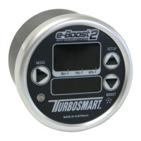
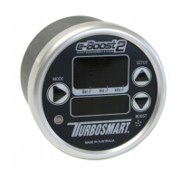
Related product manuals