EasyManua.ls Logo

Tuson TSC-1000 User Manual

Tuson TSC-1000
13 pages
To Next Page IconTo Next Page
Page #1 background imageLoading...
Page #1 background image
Installation Instructions
Tuson Sway Control
TSC-1000
475 Bunker Court
Vernon Hills, IL 60061 USA
800-968-8766
www.tusonaustralia.com.au
November 2018
US PAT. NO. 9,026,311 / 9,415,753
www.tusonrvbrakes.com
AUS PAT. NO. 2014204434 / 2016204948
Tuson RV Brakes, LLC
T
USO
N
Tuson Australia PTY LTD
T
USO
N
150 Northbourne Road
Campbellfield, VIC 3061 Australia
+61 3 9305 3484
Module
wiring
connector
on this
side.
Module will not function if improperly
positioned and/or oriented.
When
mounting,
this point
must be on
the trailer
center line.
Wires
Trailer Wire
Function
Purple
Left (driver's) side
electric brakes output
Pink
Right (curb) side
electric brakes output
White
Trailer battery/frame
ground point
Blue
Electric brake
controller signal from
tow vehicle
Black
12VDC from tow
vehicle trailer
harness
Vernon Hills, IL 60061
800-968-8766
www.tusonrvbra kes.com
!
Warning!
Read and follow all
directions in the
Installation Instructions
to ensure the unit
operates properly.
Designed and Engineered in the USA by Tuson RV Brakes, LLC
Tuson RV Brakes, LLC
T
U
S
O
N
Mount this edge parallel with the trailer axle beams
approx. 1 to 10 feet back from trailer bumper hitch ball
ON A VERTICAL FRAME SURFACE
US PAT. NO. 9,026,311 / 9,415,753
Tuson Sway Control
(P/N: TSC-1000)
Mount with this side UP
AUS PAT. NO. 2014204434 / 2016204948
Question and Answer IconNeed help?

Do you have a question about the Tuson TSC-1000 and is the answer not in the manual?

Tuson TSC-1000 Specifications

General IconGeneral
BrandTuson
ModelTSC-1000
CategoryControl Unit
LanguageEnglish

Summary

Section One: Trailer TSC Mounting

TSC Mounting Location

Explains the correct placement of the sway control unit on the trailer frame.

Mounting Hardware

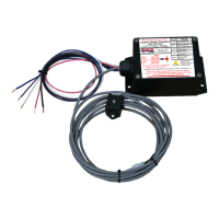
Details the necessary bolts and instructions for physically attaching the TSC unit.

Section Two: TSC Wiring

Trailer Battery Requirements

Specifies the need for a full-size 12-volt battery, not small gel-cell types.

Ground Connections

Outlines the critical process of connecting all grounds for proper TSC operation.

12 Volt Connections

Details the connection of the 12V power supply from the tow vehicle and battery.

Electric Brake (Blue Wire) Connections

Explains how to connect the blue brake signal wire from the tow vehicle.

Left and Right Side Brake Wires

Describes connecting purple (left) and pink (right) wires to respective trailer brakes.

TSC Wiring Harness Details

Provides a table of TSC wires, their functions, and required wire gauges.

Section Three: Functional Test Procedure

Testing the TSC for Correct Wiring

Step-by-step guide to verify correct electrical connections of the TSC unit.

TSC Status Light Module Explanation

Describes the TSC status light's behavior and diagnostic indicators.

Section Three: Functional Test Procedure (cont.)

Left Side Brake Wiring Test

Verifies left side brake wiring by checking specific LED flashes.

Right Side Brake Wiring Test

Verifies right side brake wiring by checking specific LED flashes.

Section Three: Status Light and Troubleshooting

Troubleshooting Guide

Lists light actions, conditions, and corrective actions for TSC issues.

Section Four: How The TSC Works

TSC Operational Principles

Explains how the TSC monitors trailer yaw and applies brakes.

Limited Warranty