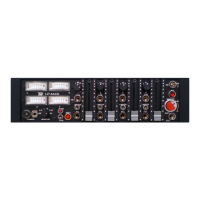
The TW LP444s is a compact, portable audio mixer designed for four-track recorders or cameras, offering switchable configurations of 4 inputs / 2 outputs or 4 inputs / 4 outputs.
Function Description:
The LP444s serves as a versatile audio interface, allowing users to connect up to four microphones or line-level sources, process their signals, and output them to recording devices or cameras. Its core functionality revolves around providing high-quality preamplification, signal routing, and dynamic control through built-in limiters. The mixer is designed for field use, indicated by its compact size, battery power option, and robust construction.
Important Technical Specifications:
- Microphone Inputs: Four balanced XLR female connectors.
- Sensitivity: -75 dBu.
- Maximum Input Level: -20 dBu.
- Microphone Power: Supports 48 V, 12 V, and T (DIN AB) phantom power.
- Line Attenuation: Adds 60 dB attenuation before the mic preamp for line-level signals.
- Signal to Noise Ratio: > 65 dB.
- Equivalent Input Noise (EIN): -125 dBu.
- Frequency Response: 20 Hz - 20 kHz ±2 dB.
- Harmonic Distortion: Less than 0.2%.
- Low-cut Filter: 80 / 100 Hz / 14 dB octave.
- Crosstalk Isolation (channel to channel): < -65 dB.
Outputs:
- Line Outputs: Transformer-balanced XLR.
- Line level on 600 Ω: 0 dB on the modulometer corresponds to +6 dBu.
- 4 on the 1-7 scaling corresponds to 0 dBu.
- 0 Vu on the VU scaling corresponds to +4 dBu.
- Unbalanced Line and Monitor Returns Maximum Output Level: +18 dBu.
General:
- Internal Power: Battery (AA size rechargeable).
- External Power: 11-25 Vdc.
- Power Consumption: 90 mA.
- Dimensions: 255 x 165 x 65 mm (10 x 6.5 x 2.6 in).
- Weight: 2 kg (4.2 lbs).
Usage Features:
Left Side Panel:
- Balanced Channel Inputs: Four electronically balanced circuits (transformer balanced optional) with XLR connectors. Pin wiring: pin1 ground, pin2 +phase signal, pin3 -phase signal.
- Microphone Powering Selector Switches: Allow selection of DYN 200 (0.2 mV, no power), 48V, 12V, or T mic powering. Selecting 48V, 12V, or T automatically introduces 10 dB of attenuation, suitable for condenser microphones.
- Phase Reverse Switches: Compensate for phase errors due to wiring or mic placement.
- Phantom On/Off Switch: Controls the 13 mA phantom power supply. Switching it off (when using dynamic, wireless, or T-powered mics) extends battery life.
- Attenuation Switches: Decrease mic preamplifier gain by -10 dB in position D, and -13 dB in positions 48, 12, and T.
- Mic/Line Level Switches: Selects mic or line level, adding -60 dB attenuation before the mic preamplifiers for line-level signals.
- Optional NP1 Battery Holder: Allows the mixer to be powered by an NP1 battery instead of internal AA batteries, depending on the panel side switch position.
Front Panel:
- 4/4 Switch: In stereo mode (switch down), the mixer operates as 4 in / 2 out. In 4/4 position, channel 1 Pan switches to L, channel 2 to R, allowing independent control of four inputs to four outputs via channel faders.
- Modulometers: Continuous lighting, peak reading meters with BBC 1-7, dB, or VU scaling. Red LEDs indicate gain reduction when limiters are active.
- 6.3 and 3.5 mm Phone Jacks: For headphone monitoring.
- Monitor Selector Switch: Offers various monitoring options: ST stereo, L+R sum, phase check, MS stereo equivalent Left (L-R difference signals), MS stereo equivalent Right (MS matrix), R right channel, L left channel. In 4/4 mode, channels L and 3, and R and 4 are linked for monitoring.
- Phones Volume Control: Adjustable output voltage into 50 Ω from 20 to 500 mV.
- Limiters On/Off Switches: Four individual limiters with fast attack time (<1 msec) and slow release time for smooth operation. Red LEDs on meters indicate limiter activation and gain reduction. Threshold is internally set to +6 dBu at the balanced output, but can be adjusted (see ADJUSTMENT POINTS).
- Battery Check Pushbutton: The R meter displays battery status (6/full, 5/power LED blinks when low, then empty).
- Reference Generator Switch: Feeds a 1 kHz sine wave signal to all four outputs. Level can be controlled at L and R outputs by the Master control; channels 3 and 4 outputs are internally set to 0 dB.
- Slate Microphone: Used for identifying recorded segments or as an emergency field microphone.
- Low-cut Filter Switches: Provides 14 dB/octave attenuation at 100 Hz.
- Pan Switches: Assigns selected input signal to Left or Right output. In M position, equal signal amount is sent to both. S position of Pan switch 1 assigns Channels 1-2 as a stereo pair controlled by Channel 1 Fader.
- Channel Gain Controls: Adjust input gain for each channel.
- Pre-Fade Listen (PFL) Pushbuttons: Allows monitoring of individual channels without interrupting the main output audio signal.
Right Side Panel:
- Balanced Outputs: Four main outputs via transformer-balanced XLR connectors. Left and Right outputs are also linked to a Hirose 10-pin multiway connector for quick connection to outputs and monitor returns. Line level is set at 0 dBu on 600 Ω and +4 dBu for VU metered mixers. Hirose 10-pin wiring: pin 1. +LEFT output, pin 2. -LEFT output, pin 3. +RIGHT output, pin 4. -RIGHT output, pin 5. RIGHT return, pin 6. N/C, pin 7. LEFT return, pin 8. N/C, pins 9., 10. GROUND.
- Unbalanced Post Fader Outputs: A TA5M 5-pin connector carries four unbalanced output signals (3 dB lower than balanced outputs) for feeding a recorder. Wiring: pin1-CH1 out, pin2-CH2 out, pin3-CH3 out, pin4-CH4 out, pin5-GROUND.
- Direct Channel Pre-Fader Outputs: Via a TA5M connector. Wiring: pin1-CH1 out, pin2-CH2 out, pin3-CH3 out, pin4-CH4 out, pin5-GROUND.
- Line/Mic Level Switches: Attenuate XLR and Hirose line levels by 50 dB to provide microphone level.
- 3.5 mm Stereo Monitor Input Jack: For external monitoring.
- Video Assist: A mono output formed by summing Left, Right, Channel 3, and Channel 4 output channels, available on a TA3M connector. It's an unbalanced signal 3 dB below the unbalanced output level. Wiring: pin1. GROUND, pin3. SIGNAL.
- Return 1 or 2 Selector Switch: In RTN1 position, the 3.5 jack and Hirose returns are selected for monitor. In RTN2 position, returns from the RTN2 3.5 jack are used by the monitoring circuits.
- EE / RTN12 Switch: A two-position switch selects direct outputs from the mixer or return 1 and 2 as a signal source for monitoring.
- Master Fader: Sets the gain for both Left and Right legs, with +6 dB of gain available beyond the nominal 0 dB gain position.
- PWR LED: A red LED indicates power is on, and blinks when the battery is low.
- Power Switch: In EXT position, the mixer is powered by an external DC supply. In BATT position, it uses internal batteries.
Maintenance Features:
- Battery Recharging: Internal batteries should be recharged with the power switch in the EXT position.
- Power Supply Protection: The DC power stabilizer includes a built-in Poly-Fuse. If tripped, it will reset after approximately 15 seconds once the power supply is disconnected.
- Adjustment Points:
- Gain and Modulometer Adjustment: Connect an AC voltmeter to the Left balanced line output. Set channel 1 pan to L, fader fully clockwise, Master to 0 dB, LFA off. Connect a 1 kHz 0 dBm attenuator –80 dB to Mic 1 Input. Adjust TRIMA1 to obtain 0 dBu (+4 dBu on VU metered mixers) at the Left balanced output. Adjust TRIMM1 on the Modulometer amplifier board for 0 dB on the Left meter. Cut input signal and switch on the Reference Generator. Adjust TRIMRG on the Ref. Gen amplifier board for 0 dB on the Left meter. Repeat for Right output/meter, and for Channels 3 and 4 outputs (with 4/4 switch up and meter selector to 3–4).
- Limiter Threshold Adjustment: Connect an AC voltmeter to the Left balanced line output. Apply a 1 kHz signal until the desired level is reached with the limiter off. Move the limiter switch to LIMITER and adjust TRIML1 until the level drops by 0.5 dB. Repeat for Right output/meter, and for Channels 3 and 4 outputs (with 4/4 switch up and meter selector to 3–4).