Daytona Twin Tec LLC, 933 Beville Road, Suite 101-H, S. Daytona, FL 32119 2005 Single Fire Coil
(386) 304-0700 www.daytona-twintec.com
4/2007
Page 2
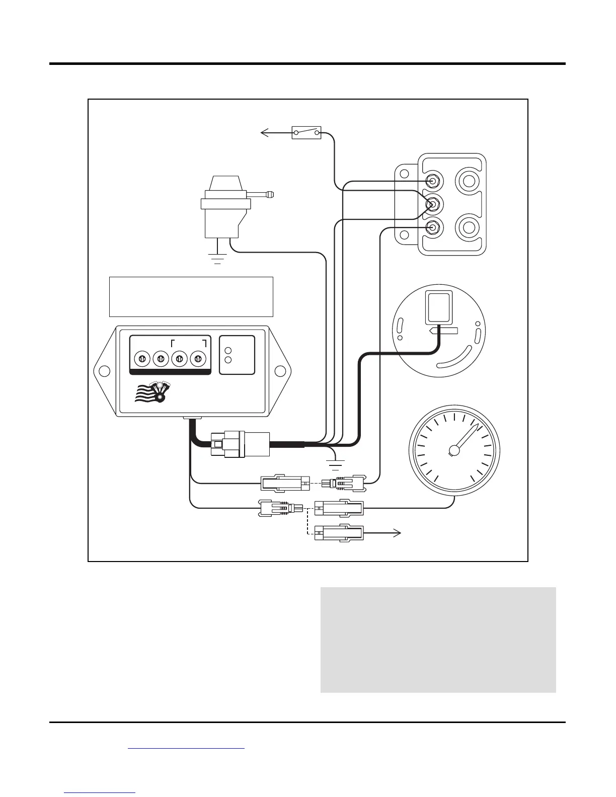
Figure 2 – Twin Tec Model 1006/1007 Single Fire Wiring Diagram
RPM
+
_ _
ENGINE
STOP/RUN
SWITCH
VOES
(VACUUM
SWITCH)
WHITE/BLACK
PINK
PURPLE/WHITE
TO
+12V
SINGLE FIRE COIL
BLUE
TO FRONT
SPARK
PLUG
TO REAR
SPARK
PLUG
OPTIONAL TACH
BROWN
OPTIONAL CABLE CONNECTED TO
BROWN TACH WIRE DURING PC LINK
TO PC
SERIAL
PORT
BLUE
BLACK
WHITE/BLACK
MODE SETTINGS FOR SINGLE FIRE
2 STREET ADVANCE CURVES, MULTI-SPARK DISABLED
3 STREET ADVANCE CURVES, MULTI-SPARK ENABLED
6 RACE ADVANCE CURVES, MULTI-SPARK DISABLED
7 RACE ADVANCE CURVES, MULTI-SPARK ENABLED
CAMSHAFT
POSITION
SENSOR
32400-80A
7
8
9
0
1
2
6
5
4
3
6
5
4
7
8
7
8
5
2
0
9
1
6
3
4
9
1
0
3
2
7
8
1
9
0
2
3
6
5
4
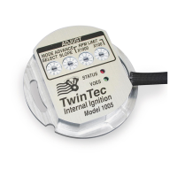
MODE
SELECT
ADVANCE
SLOPE X1000
RPM LIMIT
X100
STATUS
VOES
TwinTec
External Ignition
Model 1007
ADJUST
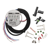
3. Apply silicone dielectric grease to the coil terminals
to reduce corrosion and prevent arcing. Make sure
that the plug wires have tight fitting boots and the
proper size terminals. If your motorcycle is still
equipped with the original carbon core suppression
plug wires, this is a good time to consider a high
quality spiral core wire set such as the Twin Tec
P/N 3003 universal set.
WARNING: To avoid ignition system
damage from coil arcing, never crank
the engine while any spark plug wire
is disconnected. Do not touch or
connect any test equipment, including
a timing light, to the coil while the
engine is running.
 Loading...